
Cutting head
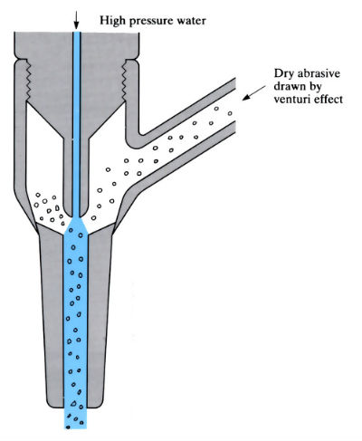
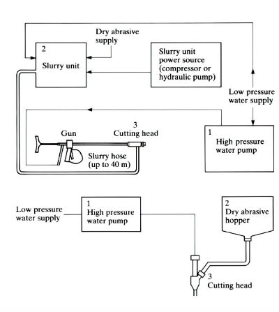
Cuts materials by means of a high pressure fluid jet (usually water, although other fluids or air alone can be used) containing abrasive particles. The abrasive material can be introduced dry or (more usually) in the form of a slurry, striking the workpiece at a velocity approaching that of sound, chipping away small particles. An abrasive jet cutting system comprises the following main operating units:
- A high pressure water pump.
- A hopper feed or slurry unit.
- A cutting head.
- A profiling/cutting machine which may be manually operated, CNC or controlled by a programmable robot.
Equipment can also be used for deburring, flash removal, cleaning, etc.
Abrasive jet cutting plan
Manufacture:
- An alternative to laser, plasma and flame cutting and blanking for cutting and profiling sheet materials. Also used for cleaning, degreasing, deburring and flash removal.
- Fluid medium, usually water at a pressure of 50–70 MPa, which may contain chemicals to minimise corrosion of material being cut. Other fluids or air sometimes used. Water, delivered at up to 300 l min-1, needs a powerful 45 kW pump.
- Abrasive is usually in the form of a slurry, although dry abrasives are sometimes used. Dry abrasives cause more problems, as they must be kept dry to avoid clogging in the feed line from hopper to cutting head.
- Abrasive material is usually builders’ sand, which is used at rates of 0.5–0.75 kg min-1, or more expensive materials such as SiC, which gives up to 3 times the cutting speed of sand.
- Particle size of abrasive varies depending on cutting speed and/or edge quality required. The finer the particle size, the cleaner the cut; the coarser the particle size, the faster the cutting speed.
- Since abrasive is one of the main operating costs, careful choice in terms of type, particle size, quantity and recycling is necessary.
- Feed rate of abrasive and water must be carefully metered, controlled and matched to the cutting head to give optimum and reliable performance. Nozzles are specially designed, depending on abrasive, material being cut, cutting speed and quality of cut. Nozzle life is usually in excess of 1000 h.
- Cutting speeds depend on pressure, abrasive type, size, type and thickness of material and quality of cut required. Cutting speed is not as high as thermal, plasma or laser cutting. Typical values are as follows:
- 12.5 mm carbon fibre: 385 mm min-1
- 6.25 mm titanium: 125 mm min-1
- 13 mm mild steel: 200 mm min-1
- 6 mm glass: 150 mm min-1
- Process has the advantage of low noise with no fumes or dust, and can be used safely in explosive environments such as the oil and mining industries.
Materials:
- Almost any material from soft, ductile materials to high tensile alloys can be cut, providing it is not affected by water, and its hardness is less than that of the abrasive. Marble, granite, stone, slate, glass, ceramics, rubber, asbestos, reinforced concrete, carbon fibre, plastics, pure metals and alloys have all been successfully cut.
- Since there is no heat generated, there is no HAZ and no microstructural changes and/or distortion that would affect mechanical properties.
Design:
- Thickness of material that can be cut varies according to production parameters, but can range from foil to 50 mm thick steel.
- Accuracy of cut depends on the optimisation of production parameters and the accuracy of the movement of the cutting head and/or workpiece. The cutting head can be fitted to CNC profiling machines, operated by programmable robots or hand-held.
- A scalloped edge is produced, similar to that produced by flame cutting but not so severe.
- Kerf width depends on nozzle design, but is usually in the range 3–8 mm.
- The cut is tapered; the thicker the material, the more pronounced the taper. The nozzle head can be tilted to give a taper on the scrap side only.
See Also: Laser cutting, Plasma arc cutting and Flame cutting.
This article is a part of Manupedia, a collection of information about some of the processes used to convert materials into useful objects.
Rate and Review
Rate this article
Review this article
Log into OpenLearn to leave reviews and join in the conversation.
Article reviews