
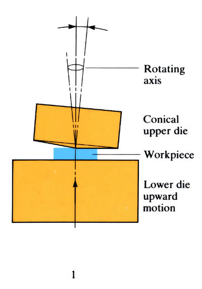
- Top die can be orbited by a few degrees (a°) about the vertical axis, while the lower die is moved upwards during the forging operation.
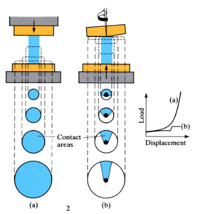
- Only a small area of contact, reduces forging loads to only 10% of that of conventional forging at the end of the stroke.
- Best used for components with large-diameter flanges.
Manufacture:
- Purpose-built machines are mainly intended for warm forging applications at 0.25–0.6Tm.
- Diameters up to 150 mm can be produced.
- Precise volume, preformed slugs are induction heated and automatically fed to the orbital forging press.
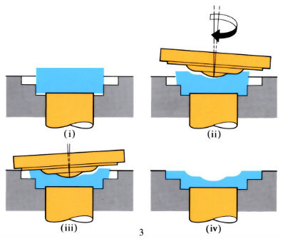
- The blank is progressively formed by an upper conical die which is inclined to and rotated about the machine axis. A lower die, capable of vertical movement only, presses the workpiece against the upper wobbling die. Therefore at any instant the tool-workpiece contact area is small and the forging loads are reduced to only 10–5% of that which is normally required. Capital cost is lower than that required for a much larger conventional forging press.
- Forging output rate can be 375–600 parts h-1.
- Orbital speed of upper die is 1000 oscillations min-1. Press tonnage 200 tonnes.
- Ejection of the forging from the die is automatic and an air blast blows it clear of the die area.
- There is minimal flash formation.
- Process has been used for cold compaction of powder preforms and powder forging applications.
Materials:
- All forgeable materials can be orbital forged.
- Materials include all carbon and low-alloy steels, stainless steels, aluminium alloys and brasses.
- Powder compacts can be orbitally forged to increase their densities to near theoretical. This is a type of powder forging.
Design:
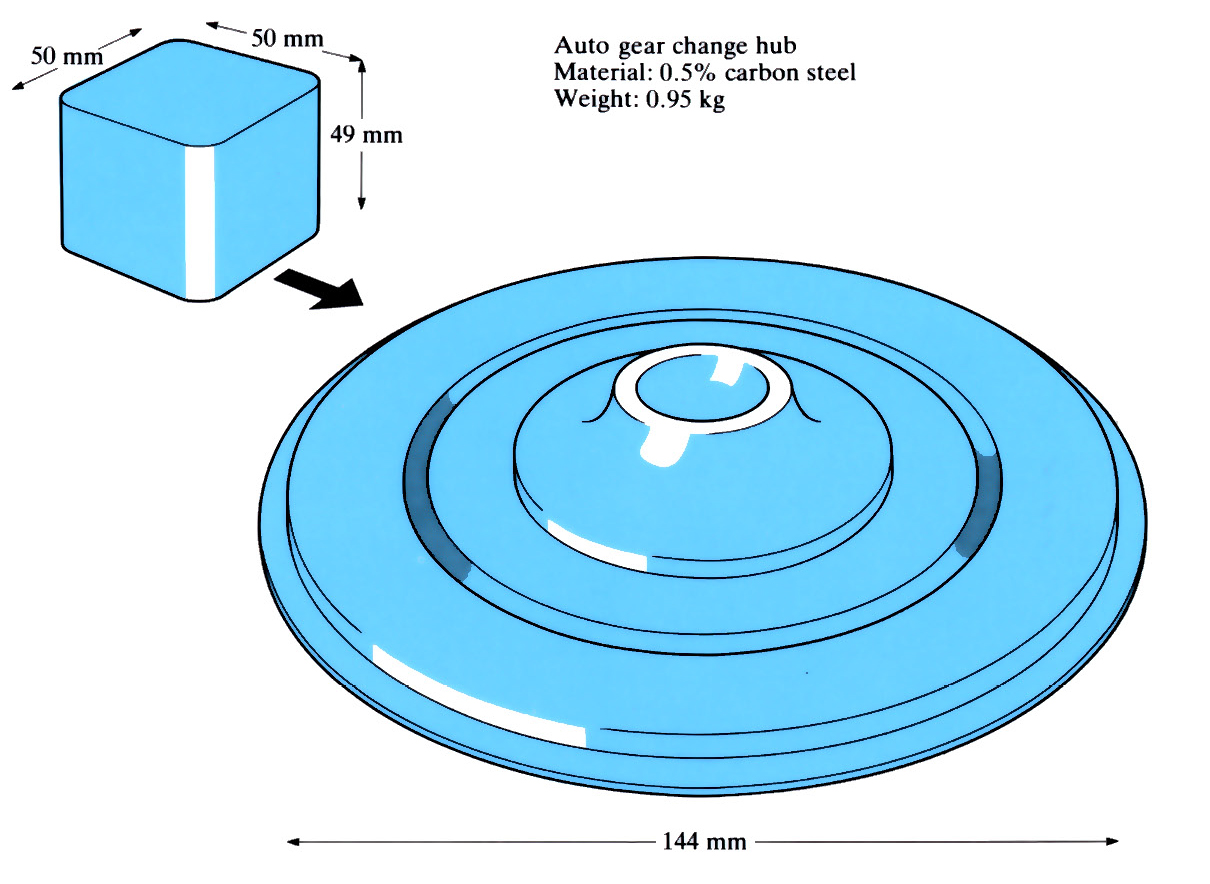
- Process is used to produce components with large-diameter flanges up to 150 mm dia.
- Components include bevel gears, claw clutch parts, wheel discs with hubs, bearing rings, rings of various contours and bearing end-covers. An example is shown below.
- Minimum practical forging thicknesses:
conventional 5 mm
orbital 2.5 mm - Thickness tolerances on warm forging of steel at 700–800˚C are ±0.15 mm.
- Reduced oxide scale formation compared with hot forging applications.
- Orbital forging should produce 25% material savings and 50% reduced energy costs.
See Also: Upset forging, Hot forging (open die) and Powder forging.
This article is a part of Manupedia, a collection of information about some of the processes used to convert materials into useful objects.
Rate and Review
Rate this article
Review this article
Log into OpenLearn to leave reviews and join in the conversation.
Article reviews