
Find out more about The Open University's Science courses and qualifications
Machine moulded
In modern foundries, moulds of small and medium sizes are prepared by machines. For mass-production, match-plate patterns are used with the cope pattern attached to an aluminium plate and the drag pattern on the other side of the plate. The plate fits between cope and drag. Ramming of sand can be done by machine. Holes are produced by the use of cores.
Hand-rammed
Hand-ramming of sand depends on operator skill. Accuracy is usually poor, and this is usually countered by generous machining allowances. Repeatability and surface finish are poor.
Manufacture:
- Foundry sands are usually a blend of silica grains (SiO2), 5–20% clay or bentonite and water (2–8%).
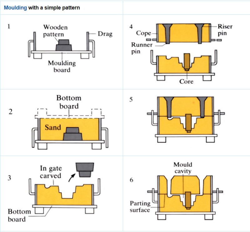
- Sand is moulded by hand or machined, around a wooden or metal pattern that can be withdrawn to leave a cavity of the required shape in the sand. To facilitate this, the moulds are usually split into two or more parts and the patterns tapered (5 mm m-1). Yields are 40–50%, cast weights range from 100 g to 100 tonnes.
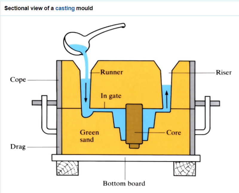
- Access to the mould cavity for molten metal entry is provided via a pouring basin sprue, runner, riser and in-gate system moulded in the top and bottom halves of the mould.
- Cores are used to form holes in the castings. They are placed in the split moulds after pattern removal. Usually, cores are made by dry sand moulding techniques. Core sand is mixed with oil, organic bonding material and water. They are moulded in core boxes, then removed and baked at 170–230 ˚C. A newer method of making cores is to bind the core by passing CO2 through it.
- A wide range of productivity is obtainable from machine mouldings using apparatus such as hand-operated “jolt-squeeze” to massive industrial plant. Plant and tooling costs are always high.
- Chemically bonded sands (sodium silicate/CO2 process) produce hard moulds with good dimensional accuracy, but which are intolerant of pattern work inaccuracies. The sand is not easily recycled.
Materials:
- Most metals and alloys (except the reactive and refractory metals such as titanium and tungsten), can be sand cast in air.
- Cast irons (Fe/1.5–4.5%C) are cast at 1200–1480 ˚C. Grey cast irons contain flake graphite particles, which give good vibration properties. This is to the detriment of strength and ductility. Much of the ductility can be regained by changing the graphite into a less detrimental globular or spheroidal form. This is achieved by inoculating the melt, just before casting, with a small amount of magnesium.
- Because of their higher melting point, steels are not favoured as casting alloys.
- The second biggest group of casting alloys are the aluminium based alloys. Aluminium/silicon alloys are the most castable alloys, with the eutectic composition (12% silicon) the most favourable. A major problem with aluminium castings is the relatively high shrinkage that occurs during solidification.
- Copper-based alloys are sand cast with additions of zinc, tin and lead.
- When casting cast iron, the moulding material has added coal dust; this type of green sand is black. When “natural” sands are used (silica sand deposits containing the clay with which they were found, or sedimentary deposits, the clay acting as its own “natural” binder) other colours are found. For instance, “Bromsgrove Red” is a popular natural moulding sand, dug direct from the ground and delivered to the factory. This type of green sand is red.
Design:
- The size and shape of the pattern must take into account the relative amount of shrinkage and the change in shape that can occur on solidification.
Approximate shrinkages for some casting alloy.
Alloy Shrinkage (mm m-1)
Cast iron
10
Steel
20
Brass
15
Aluminium
13
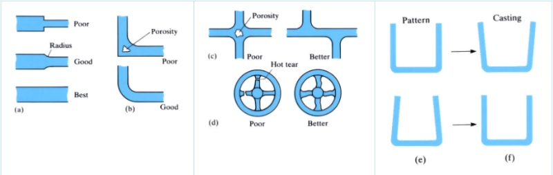
Magnesium-based 13 - The shape of the casting should allow for progressive solidification, from the remotest parts backwards. When wall-thickness variations are essential, the transition is improved by applying generous radii, Figure (a). Small radii or sharp corners act as stress raisers in the finished casting, and may also prevent proper feeding during solidification. Localised heavy cross-sections, Figure (b), create hot spots where the molten metal only solidifies after adjacent zones have frozen, creating shrinkage cavities. Applying a radius to the outer surface, or offsetting the ribs, Figure (c), alleviates this problem. Low melting point constituents cause hot tears, Figure (d), so S-shaped spokes are used. The pattern must be shaped as in Figure (e), to give a casting of the required shape, Figure (f).
Study a free course
-

An introduction to design engineering
Learn more to access more details of An introduction to design engineeringThis free course, An introduction to design engineering, looks at the way in which engineers use ideas and approaches from the discipline of design thinking to inform their work. The complexity that people bring to design problems is introduced, along with some basic methods of dealing with such complexity.
Level: 1 Introductory
-

Discovering chemistry
Learn more to access more details of Discovering chemistryChemistry lies at the centre of our modern life, playing a part in areas as diverse as the development of new drugs and materials, analysing our environment through to more mundane activities such as washing your clothes and making your tea. But to truly understand the role chemistry plays you need to have a sound grasp of a number of ...
Level: 1 Introductory
-
Particle physics
Learn more to access more details of Particle physicsThis free course, Particle physics, will give you an overview of current concepts and theories in the field. You will learn about the fundamental components of matter – known as leptons and quarks – and the composite particles, such as protons and neutrons, which are composed of quarks. You will see that all particle reactions may be described ...
Level: 1 Introductory
Rate and Review
Rate this article
Review this article
Log into OpenLearn to leave reviews and join in the conversation.
Article reviews