Use 'Print preview' to check the number of pages and printer settings.
Print functionality varies between browsers.
Printable page generated Sunday, 26 July 2026, 2:12 PM
Study Session 5 Water Treatment Technologies for Large-scale Water Supply
Introduction
In previous study sessions you have learned about sources of water, how they can become contaminated and about ways of protecting them. Even with source protection it is often necessary to treat water to ensure it is safe. This is the case at household level, which is discussed in Study Session 10, and when supplying water for towns and cities. In this study session, you consider the need for large-scale water treatment and the stages of treatment for urban water supply. You will also learn about the management of wastes produced in the process of water treatment, and consider the issues of sustainability and resilience in relation to large-scale water treatment.
Learning Outcomes for Study Session 5
When you have studied this session, you should be able to:
5.1 Define and use correctly all of the key words printed in bold. (SAQ 5.1)
5.2 Describe the different stages in the water treatment process. (SAQs 5.1 and 5.2)
5.3 Describe how the wastes from water treatment plants are disposed of. (SAQ 5.3)
5.4 Suggest how water treatment technologies can be made sustainable and resilient. (SAQ 5.4)
5.5 Undertake basic calculations in relation to water supply. (SAQ 5.5)
5.1 The need for large-scale water treatment
Water treatment is the process of removing all those substances, whether biological, chemical or physical, that are potentially harmful in water supply for human and domestic use. This treatment helps to produce water that is safe, palatable, clear, colourless and odourless. Water also needs to be non-corrosive, meaning it will not cause damage to pipework.
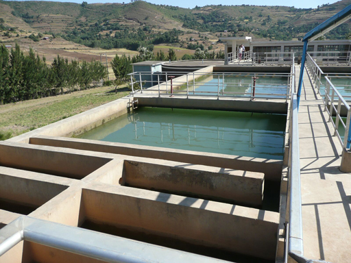
In urban areas, many people live close together and they all need water. This creates a demand for large volumes of safe water to be supplied reliably and consistently, and this demand is growing. As urban populations increase, there is a need to find new sources to meet the growing demand. If groundwater is available this can often be used with minimal treatment but any surface water source will need to be treated to make it safe. For towns and cities, the water supply is then best provided by large mechanised water treatment plants (Figure 5.1) that draw water from a large river or reservoir, using pumps. (‘Mechanised’ means that machines, such as pumps and compressors, are used). The treated water is then distributed by pipeline, as you learned in Study Session 1.
The size of the treatment plant required is determined by the volume of water needed, which is calculated from the number and type of users and other factors. Section 5.6 explains how this calculation is made but first you will look at the main stages in the water treatment process.
5.2 Stages in large-scale water treatment
There are often seven steps (Figure 5.2) in large-scale water treatment for urban municipal water supply (Abayneh, 2004). Each of the steps will be described in turn in this section. The water utility (the organisation that runs the treatment plants and water distribution system) will ensure by regular analysis of the water that it adheres to quality standards for safe water. (Water quality standards will be described in Study Session 9.)

5.2.1 Screening
To protect the main units of a treatment plant and to aid in their efficient operation, it is necessary to use screens to remove any large floating and suspended solids that are present in the inflow. These materials include leaves, twigs, paper, rags and other debris that could obstruct flow through the plant or damage equipment. There are coarse and fine screens.
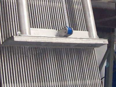
Coarse screens (Figure 5.3) are steel bars spaced 5–15 cm apart, which are employed to exclude large materials (such as logs and fish) from entering the treatment plant, as these can damage the mechanical equipment. The screens are made of corrosion-resistant bars and positioned at an angle of 60º to facilitate removal of the collected material by mechanical raking.
Fine screens, which come after the coarse screens, keep out material that can block pipework at the plant. They consist of steel bars which are spaced 5–20 mm apart. A variation of the fine screen is the microstrainer (Figure 5.4) which consists of a rotating drum of stainless steel mesh with a very small mesh size (ranging from 15 µm to 64 µm, i.e. 15–64 millionths of a metre). Suspended matter as small as algae and plankton (microscopic organisms that float with the current in water) can be trapped. The trapped solids are dislodged from the fabric by high-pressure water jets using clean water, and carried away for disposal.

5.2.2 Aeration
After screening, the water is aerated (supplied with air) by passing it over a series of steps so that it takes in oxygen from the air. This helps expel soluble gases such as carbon dioxide and hydrogen sulphide (both of which are acidic, so this process makes the water less corrosive) and also expels any gaseous organic compounds that might give an undesirable taste to the water. Aeration also removes iron or manganese by oxidation of these substances to their insoluble form. Iron and manganese can cause peculiar tastes and can stain clothing. Once in their insoluble forms, these substances can be removed by filtration.
In certain instances excess algae in the raw water can result in algal growth blocking the sand filter further down the treatment process. In such situations, chlorination is used in place of, or in addition to, aeration to kill the algae, and this is termed pre-chlorination. This comes before the main stages in the treatment of the water. (There is a chlorination step at the end of the treatment process, which is normal in most water treatment plants). The pre-chlorination also oxidises taste- and odour-causing compounds.
5.2.3 Coagulation and flocculation
After aeration, coagulation takes place, to remove the fine particles (less than 1 µm in size) that are suspended in the water. In this process, a chemical called a coagulant (with a positive electrical charge) is added to the water, and this neutralises the negative electrical charge of the fine particles. The addition of the coagulant takes place in a rapid mix tank where the coagulant is rapidly dispersed by a high-speed impeller (Figure 5.5).
Since their charges are now neutralised, the fine particles come together, forming soft, fluffy particles called ‘flocs’. (Before the coagulation stage, the particles all have a similar electrical charge and repel each other, rather like the north or south poles of two magnets.) Two coagulants commonly used in the treatment of water are aluminium sulphate and ferric chloride.
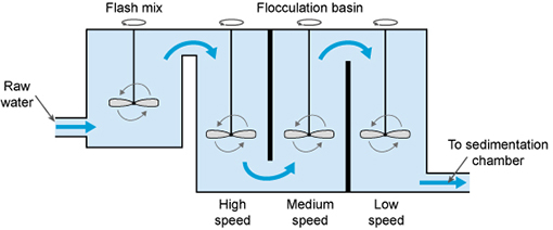
The next step is flocculation. Here the water is gently stirred by paddles in a flocculation basin (Figure 5.5) and the flocs come into contact with each other to form larger flocs.
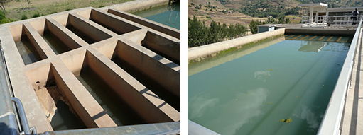
The flocculation basin often has a number of compartments with decreasing mixing speeds as the water advances through the basin (Figure 5.6(a)). This compartmentalised chamber allows increasingly large flocs to form without being broken apart by the mixing blades. Chemicals called flocculants can be added to enhance the process. Organic polymers called polyelectrolytes can be used as flocculants.
5.2.4 Sedimentation
Once large flocs are formed, they need to be settled out, and this takes place in a process called sedimentation (when the particles fall to the floor of a settling tank). The water (after coagulation and flocculation) is kept in the tank (Figure 5.6(b)) for several hours for sedimentation to take place. The material accumulated at the bottom of the tank is called sludge; this is removed for disposal.
5.2.5 Filtration
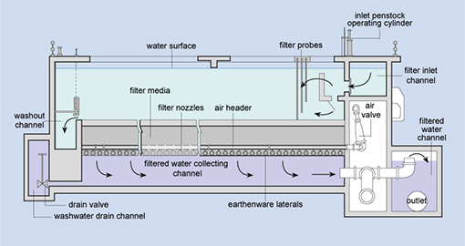
Filtration is the process where solids are separated from a liquid. In water treatment, the solids that are not separated out in the sedimentation tank are removed by passing the water through beds of sand and gravel. Rapid gravity filters (Figure 5.7), with a flow rate of 4–8 cubic metres per square metre of filter surface per hour (this is written as 4–8 m–3 m–2 h–1) are often used.
When the filters are full of trapped solids, they are backwashed. In this process, clean water and air are pumped backwards up the filter to dislodge the trapped impurities, and the water carrying the dirt (referred to as backwash) is pumped into the sewerage system, if there is one. Alternatively, it may be discharged back into the source river after a settlement stage in a sedimentation tank to remove solids.
5.2.6 Chlorination
After sedimentation, the water is disinfected to eliminate any remaining pathogenic micro-organisms. The most commonly used disinfectant (the chemical used for disinfection) is chlorine, in the form of a liquid (such as sodium hypochlorite, NaOCl) or a gas. It is relatively cheap, and simple to use. When chlorine is added to water it reacts with any pollutants present, including micro-organisms, over a given period of time, referred to as the contact time. The amount of chlorine left after this is called residual chlorine. This stays in the water all the way through the distribution system, protecting it from any micro-organisms that might enter it, until the water reaches the consumers.
World Health Organization Guidelines (WHO, 2003) suggest a maximum residual chlorine of 5 mg l–1 of water. The minimum residual chlorine level should be 0.5 mg l–1 of water after 30 minutes’ contact time (WHO, n.d.). There are other ways of disinfecting water (e.g. by using the gas ozone, or ultraviolet radiation) but these do not protect it from microbial contamination after it has left the water treatment plant. Following disinfection the treated water is pumped into the distribution system.
5.2.7 Supplementary treatment
Supplementary treatment may sometimes be needed for the benefit of the population. One such instance is the fluoridation of water, where fluoride is added to water. It has been stated by the World Health Organization that ‘fluoridation of water supplies, where possible, is the most effective public health measure for the prevention of dental decay’ (WHO, 2001). The optimum level of fluoride is said to be around 1 mg per litre of water (1 mg l–1).
On the other hand, as you learned in Study Session 2, in the Rift Valley of Ethiopia, the water resources contain a higher concentration of fluoride than is desirable. Tekle-Haimanot et al. (1995) found that the level of fluoride in drinking water from deep wells there ranged from 1.5 to 36 mg l–1. The safe level for fluoride is 1.5 mg l–1.
What does excess fluoride in the water lead to?
As mentioned in Study Session 2, in children it can cause mottling of teeth and prolonged exposure can cause skeletal fluorosis and crippling.
In such high-fluoride areas, removal or reduction of fluoride (termed defluoridation) is essential. The simplest way of doing this is to blend the high-fluoride water with water that has no (or very little) fluoride so that the final mixture is safe. If this is not possible, technical solutions may be applied. Two of these, the Nakuru Method and the Nalgonda Technique, used in Ethiopia, are described below.
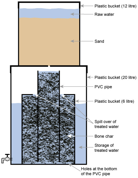
The Nakuru Method (Figure 5.8) involves a filter with bone char (charcoal produced from animal bone) and calcium phosphate to adsorb the fluoride (Kung, 2011). There have been reservations on the use of bone char, and alternatives for defluoridation, such as activated alumina, are being tested in Addis Ababa (Alemseged, 2015).
The Nalgonda technique for defluoridation (Suneetha et al., 2008) uses aluminium sulphate and calcium oxide to remove fluoride. The two chemicals are added to and rapidly mixed with the fluoride-contaminated water and then the water is stirred gently. Flocs of aluminium hydroxide form and these remove the fluoride by adsorption and ion exchange. The flocs are then removed by sedimentation.
5.3 Management of wastes from water treatment plants
From the water treatment process that you have just studied, make a list of the different wastes that arise.
You probably thought of the screenings from the coarse and fine screens, the sludge from the sedimentation tank, and backwash from the rapid gravity sand filter. There will be other wastes, such as packaging from chemicals used (typically plastic drums) and replacement equipment (which may come in wooden or cardboard boxes).
Coarse screenings are usually sent to a landfill or other waste disposal site. Fine screenings (in the form of a slurry) may be discharged to a sewer, if there is one, or sent to a landfill. The sludge from the sedimentation tank can be sent to landfill, or to a sewage treatment plant. In the latter it is added to the incoming sewage, where it can help settlement of solids.
The backwash from the sand filter is discharged into the sewer or returned to the river after settlement of solids. Packaging waste such as chemical drums can be returned to the supplier for reuse. Wood and cardboard waste can be recycled.
5.4 Sustainability and resilience in water treatment
In Study Session 4 you read about some factors that can influence the sustainability of a water source. For example, reducing soil erosion by planting trees and retaining vegetation can reduce the amount of silt that accumulates in a reservoir and prolong its life.
For the water treatment process itself to be sustainable (meaning that it can be maintained at its best for a long time) it has to be simple to operate and maintain. Complex systems should be avoided and wherever possible locally available materials should be used. For example, if a coagulant is required, the one that can be purchased in-country will be preferable to one that has to be imported. Water treatment plants consume energy, and if this energy could be supplied through renewable sources (such as solar or wind) it will keep operating costs down and improve sustainability.
The plant and distribution system should be made of robust materials that will have a long operating life. It can be difficult to obtain spare parts, so there should be plans in place for procurement of replacements. (These and other management issues are the subject of the next study session.) Another important factor in sustainability is an effective maintenance system, which needs planning and, importantly, requires well-trained and motivated staff.
Resilience, in the context of a water treatment system, is its ability to withstand stress or a natural hazard without interruption of performance or, if an interruption does occur, to restore operation rapidly. With water treatment plants located very close to water sources, having too much water can be just as much a problem for operations as having too little. Storms and floods, exacerbated by climate change, may overwhelm systems and interrupt operations, so appropriate flood defence measures must be in place. The need to be resilient to these impacts is another reason why the equipment and construction of the plant should be of a high standard.
5.5 Basic calculations in water supply
A critical factor in the sustainability of a water supply system is ensuring that the volume of water provided is sufficient to meet current and future demand. Table 5.1 shows the water supply requirements for towns of different sizes in Ethiopia according to the Growth and Transformation Plan II.
| Urban category | Population | Minimum water quantity (litres per person per day) | Maximum fetching distance (m) |
| 1 Metropolitan | >1,000,000 | 100 | – |
| 2 Big city | 100,000–1,000,000 | 80 | – |
| 3 Large town | 50,000–100,000 | 60 | – |
| 4 Medium town | 20,000–50,000 | 50 | – |
| 5 Small town | <20,000 | 40 | 250 |
The water needs of a town can be estimated from the size of the population and the water requirements of users such as schools, health facilities and other institutions within it. The guidelines for the water supply requirement of different categories of towns, shown in Table 5.1, may be used to estimate the minimum quantity of water that should be supplied for a given population.
Consider a town with a population of 60,000. What would be the minimum amount of water required?
From Table 5.1, the minimum amount of water needed per person would be 60 litres a day. So, with a population of 60,000, the daily total supply would need to be:
60 litres x 60,000 = 3,600,000 litres, or 3600 m3.
There will be institutions in the town with particular water requirements. Table 5.2 shows the requirements of some of these in Ethiopia.
| Institution | Water requirement (litres per person per day) |
| Health centre | 135 |
| Hospital | 340 |
| Day school | 18.5 |
| Boarding school | 135 |
| Office | 45 |
| Restaurant | 70 |
Once the consumers’ total water requirement has been calculated, an allowance should be added for leakage losses, and for water use by the water utility itself (for washing of tanks, etc.). This allowance could, for example, be 15%.
The water will have to be stored in service reservoirs. As you learned in Study Session 1, service reservoirs have to hold a minimum of 36 hours’ or 1.5 days’ water supply.
Box 5.1 shows a calculation of water requirement and service reservoir size for a hypothetical town.
Box 5.1 Water provision for a small town
Imagine a town with a population of 5000 people, and a health centre that treats 100 people a day.
The minimum water requirement per day for the population (using the guidelines in Table 5.1) will be 40 litres x 5000 = 200,000 litres, or 200 m3.
The water requirement for the health centre would be 135 litres x 100 = 13,500 litres, or 13.5 m3. The total water requirement each day would be 200 + 13.5 = 213.5 m3.
Allowing for 15% leakage and water usage by the water utility, each day the required volume of treated water supplied would be:
213.5 m3 x 1.15 = 245.5 m3. This could be rounded up to 246 m3.
The service reservoir would need to hold a minimum of 36 hours’ of supply (1.5 days). This means that the service reservoir size would be:
246 m3 x 1.5 = 369 m3. This could be rounded up to 370 m3.
The water requirement would therefore be 246 m3 per day, and the minimum service reservoir capacity required would be 370 m3. This volume could be held in one service reservoir or shared between two, located in different parts of the town.
These simple calculations are included here to give you an idea of the approach that would be taken to planning a new water supply system. In practice, the process would require many different engineering, economic and environmental considerations involving a team of experts.
Summary of Study Session 5
In Study Session 5, you have learned that:
- Large-scale water treatment is required when the population needing water is large and surface water sources have to be used. Large-scale water treatment often involves seven stages.
- Screening involves trapping large floating and suspended solids using bar screens or devices such as microstrainers.
- Aeration helps expel any acidic gases and gaseous organic compounds from the water. Aeration also removes iron and manganese. Pre-chlorination is carried out instead of, or in addition to, aeration if there are excess algae in the raw water. The chlorine also oxidises taste- and odour-causing compounds.
- Coagulation is used to remove fine particles smaller than 1 µm in diameter. Aluminium sulphate and ferric chloride are two coagulants commonly used in water treatment.
- The next process is flocculation, where the water is stirred gently to enable large flocs to form.
- Once the large flocs have formed, the water goes to a sedimentation tank where the flocs settle out. Filtration follows sedimentation.
- After filtration the water is disinfected by chlorine. The chlorine stays in the water and protects it till it reaches the consumers.
- Supplementary treatment includes fluoridation of the water, to protect teeth. Defluoridation may be necessary in some areas to reduce excessive fluoride to safe levels.
- The wastes from a water treatment plant include screenings, sludge, backwash waters and packaging from the supply of chemicals and equipment.
- Sustainability in water treatment is enhanced by using simple processes, locally available materials, regular training of staff, designing for future water demand, using robust equipment and the use of renewable energy.
- Resilience of water treatment plant can be helped by taking protective measures against natural hazards and ensuring that all equipment and construction is of a high standard.
- Basic calculations for water supply can be carried out if the size of the population to be served and other water demands are known.
Self-Assessment Questions (SAQs) for Study Session 5
Now that you have completed this study session, you can assess how well you have achieved its Learning Outcomes by answering these questions.
SAQ 5.1 (tests Learning Outcomes 5.1 and 5.2)
Match the following words to their correct definitions.
Two lists follow, match one item from the first with one item from the second. Each item can only be matched once. There are 21 items in each list.
defluoridation
sustainable
water utility
coagulant
coarse screens
coagulation
sedimentation
pre-chlorination
filtration
fluoridation
water treatment
disinfection
resilience
mechanised
flocculation
fine screens
flocculant
microstrainer
residual chlorine
aerated
contact time
Match each of the previous list items with an item from the following list:
a.settling of solids
b.the process by which harmful substances are removed from water so that it is safe for human consumption
c.the ability to withstand stress or a natural hazard
d.the organisation that is responsible for producing and distributing drinking water
e.able to be maintained at its best for many years
f.chlorination before the main treatment stages of the water purification process
g.separation of solids from a liquid
h.the process whereby the size of particles increases as a result of particle combining together
i.the addition of fluoride
j.a rotating drum with a stainless steel fabric with a stainless steel fabric with a mesh size ranging from 15 µm to 64 µm
k.the neutralisation of the electrical charge of particles by using a coagulant
l.steel bars that have a spacing of 5–15 cm
m.the amount of chlorine left after all the pollutants have reacted with it
n.the elimination of micro-organisms that can cause disease
o.the duration for which the water undergoing treatment is exposed to a disinfectant
p.supplied with air
q.a chemical that assists the process of flocculation
r.where machines are used to carry out a function
s.removal of excess fluoride from water
t.a chemical used in water treatment to neutralise the charge on fine particles
u.steel bars with a spacing of 5–20 mm
- 1 = s,
- 2 = e,
- 3 = d,
- 4 = t,
- 5 = l,
- 6 = k,
- 7 = a,
- 8 = f,
- 9 = g,
- 10 = i,
- 11 = b,
- 12 = n,
- 13 = c,
- 14 = r,
- 15 = h,
- 16 = u,
- 17 = q,
- 18 = j,
- 19 = m,
- 20 = p,
- 21 = o
SAQ 5.2 (tests Learning Outcome 5.2)
Imagine you have to inform the local population of the new water treatment plant that is to be built in their town. Draw a simple flow diagram to show the different stages of treatment, and write one or two sentences to describe what happens and why at each of the stages.
Answer
Your diagram should look something like Figure 5.9.
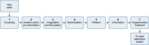
Stage 1 Screening removes large floating and suspended solids, which can damage equipment in the plant, or block pipework.
Stage 2 Aeration expels acidic gases such as carbon dioxide and hydrogen sulphide, and gaseous organic compounds that can give an unpleasant taste to the water. Aeration also oxidises iron and manganese to their solid form so that they can be removed, thereby eliminating bad flavour and staining. If excess algae are present in the raw water, pre-chlorination is carried out. The chlorine also oxidises compounds that cause taste and odour.
Stage 3 Coagulation neutralises the negative electrical charge in particles in the water, which enables the particles to come together to form flocs. Flocculation results in large flocs forming.
Stage 4 The large flocs formed during flocculation settle out in the sedimentation stage, leaving largely clear water.
Stage 5 Any solids remaining in the water after sedimentation are removed during filtration.
Stage 6 The water is then chlorinated to kill any pathogenic micro-organisms present.
Stage 7 Supplementary treatment, such as the addition of fluoride, or the reduction of the fluoride level, then takes place.
SAQ 5.3 (tests Learning Outcome 5.3)
Recalling your study of the wastes produced during water treatment, assign the different wastes to the management options shown below.
| Management option | Waste |
| Sent to landfill | |
| Recycled | |
| Discharged to sewer | |
| Reused | |
| Taken to a sewage treatment plant |
Answer
You should have identified the following wastes for each option.
| Management option | Waste |
| Sent to landfill | Coarse screenings; fine screenings (if no sewer present); sludge from the sedimentation tank |
| Recycled | Plastic chemical drums |
| Discharged to sewer | Fine screenings; backwash from the rapid gravity sand filter |
| Reused | Wooden and cardboard packaging |
| Taken to a sewage treatment plant | Sludge from the sedimentation tank |
SAQ 5.4 (tests Learning Outcome 5.4)
Which of the following statements do not contribute to the attainment of sustainability and resilience in a water treatment plant? Give reasons for your choice.
- a.using locally available materials
- b.making sure the plant is protected from natural hazards
- c.using a diesel generator for running the pumps and compressors
- d.using simple systems where possible
- e.using the cheapest equipment that is in the market.
Answer
c. Using a diesel generator for running the pumps and compressors will not contribute to sustainability and resilience. Diesel is a non-renewable source of energy and will run out in time. It is better to use a renewable source of energy, for example electricity generated by solar or wind power.
e. Using the cheapest equipment that is on the market will also not contribute to sustainability and resilience. The cheapest equipment is often the least robust and is likely to fail before long.
SAQ 5.5 (tests Learning Outcome 5.5)
Gideon, a new urban WASH worker, needs guidance on how to calculate the water requirement and service reservoir size in a new area that is to be developed in a town that already has a population of 150,000. In this new area, the population will be 30,000, and there will be three new health centres. The three health centres together will treat 250 people a day. There will also be a day school for 1500 pupils.
Draw up the calculations to show Gideon how it’s done.
Answer
Using data from Tables 5.1 and 5.2, the water requirement each day for the extra population will be 80 litres x 30,000 = 2,400,000 litres, or 2400 m3.
The three health centres will need 135 litres x 250 = 33,750 litres a day, or 33.75 m3 a day.
The day school will need 18.5 litres x 1500 = 27,750 litres a day, or 27.75 m3 a day.
The total additional water requirement will be 2400 + 33.75 + 22.75 = 2461.5 m3.
With allowance for leakage, etc. the water requirement will be 2461.5 m3 x 1.15 = 2830.7 m3, say, 2831 m3.
The service reservoir has to hold 2831 m3 x 1.5 = 4246.5 m3, say, 4247 m3.
Thus, the water requirement in the new area would be 2831 m3 per day, and the size of service reservoir required would be 4247 m3.