

2.2 Fibre types
A strand of glass (or plastic, but the best performance comes from glass) has a core surrounded by a cladding, where the refractive index of the glass in the core is higher than that of the cladding (see the box on ‘Refractive index>’).
Light is contained within the core by total internal reflection, which is the effect that a light ray will be completely reflected at the interface from a high refractive index material to a low refractive index material, if the angle between the light ray and the interface is small enough.
Refractive index
The core of an optical fibre has ‘different properties’ from the cladding. Specifically, the property that differs is the refractive index. The refractive index of a material, usually written as n, determines the speed of propagation of light in that material such that the speed, v, in the material is related to the speed in free space, c, by
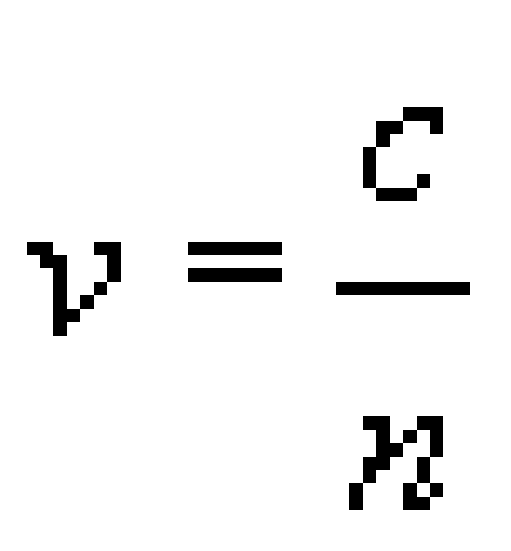
The refractive index of air is very close to 1.0 as the speed of light in air is very close to speed of light in a vacuum (free space), and the refractive index of most optical glasses is around 1.5. In optical fibre the chemical composition of the glass in the core is different from that of the cladding, so that the refractive index of the core is very slightly greater than that of the cladding.
Experiment: Total internal reflection
You can do a simple experiment in the bath to demonstrate total internal reflection if you have a waterproof torch (or a torch you can seal in a transparent plastic bag).
You might be sceptical about doing this experiment, but I would commend it to you to reinforce the concept of total internal reflection. Please, though, remember that electricity and water can be dangerous. Only do the experiment with a battery-powered torch.
Fill the bath with water to a level where the torch can be fully submerged. With the room dark enough so that you can easily see where the torch beam is shining, put the torch in the water and point it towards the surface. Start at a steep angle (pointing almost directly upwards) then gradually reduce the angle, watching where the light beam goes (Figure 2a). Some light comes out of the water and some is reflected off the surface, but as the angle gets smaller, approaching the horizontal, you should see that the beam emerging from the water gets closer to the water surface, until eventually no light emerges at all and all the light is reflected back down off the surface (Figure 2b). This is total internal reflection, which occurs because the refractive index of water is higher than that of air.
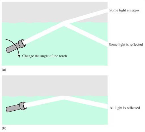
For comparison, take the torch out of the water and do the experiment the other way round, shining the beam into the water. In this case you should find that although as the angle gets smaller more of the light is reflected off the water surface, some light always enters the water. You do not get ‘total external reflection’.
While in principle optical fibre could use the boundary between the glass and air to contain the light – like you have demonstrated using the boundary between water and air – in practice the performance is very much better when using the boundary between the core and cladding glass, which can be controlled more accurately and is protected from damage.
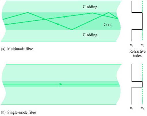
The basic types of optical fibre are single-mode and multimode, and are sketched in cross-section in Figure 3. Multimode fibre has a larger diameter core than single-mode, and, in simplistic terms, multimode fibre allows many different light paths (‘modes’) whereas single-mode allows only one. The significance of this difference will become clearer later.
This idea of the modes in a fibre being different paths that rays can follow is known as the ‘ray model’ of light propagation. The model is useful for a qualitative understanding of the propagation of light in fibre, and can even be used for some quantitative analysis, but a complete understanding of light in fibre requires consideration of the electromagnetic fields.
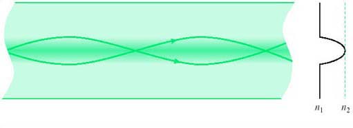
Both the fibres drawn in Figure 3 are what is known as step-index fibres, because the refractive index changes from core to cladding in a single step (abruptly). An alternative construction used for multimode fibre is graded-index (Figure 4), in which the refractive index varies smoothly from a maximum down the fibre axis to a minimum in the cladding. There are advantages to using graded-index fibre rather than step-index multimode fibre which will be considered later, and the fibre used for telecommunications purposes is nearly always either single-mode fibre or graded-index multimode fibre.
There are three types of fibre widely used for telecommunications (all three types have the same cladding diameter of 125 μm):
Single-mode step-index fibre with a cladding diameter of 125 μm and a core of about 10 μm. Specifications for fibres of this type are to be found in IEC 60793-2-50:1992 type B1 and ITU-T G.652, G.653, G.654 and G.655 (see References).
Multimode graded-index fibre with a cladding diameter of 125 μm and a core of about 50 μm. Specifications for fibres of this type are to be found in IEC 60793-2-10:1992 type A1a and ITU-T G.651.
Multimode graded-index fibre with a cladding diameter of 125 μm and a core of about 62.5 μm. Specifications for fibres of this type are to be found in IEC 60793-2-10:1992 type A1b.
The IEC specifications are generally used in LANs, and the ITU-T specifications for transmission in the core network. The differences between the several ITU-T specifications for single-mode fibre are to do with their dispersion characteristics, and are discussed later in Section 2.4.
Broadly speaking, the 10/125 μm single-mode fibre has the highest performance but is the most difficult to use, because the small core makes joints more difficult (notice the way of describing the fibre by ‘core-diameter/cladding diameter’, such as ‘10/125 μm’. Later I shall abbreviate further, referring to ‘10 μm’ fibre). The 50/125 μm multimode fibre is easier to use but has inferior performance (higher loss and smaller usable bandwidth). The 62.5/125 μm multimode fibre is the easiest to use but has the lowest performance. The characteristics of 50/125 μm and 62.5/125 μm fibre are quite similar, however, and in practice the difference tends to be just that the former has been used in Europe and the latter in the USA.
SAQ 3
These days telecommunications transmission in the core network invariably uses 10/125 μm single-mode fibre whereas LANs have mostly used one of the two multimode fibres. Why do you think this is?
Answer
Transmission systems in the core network need to transmit over longer distances than is needed in LANs, so the lower loss of single-mode fibre is a particular advantage, and it is worth the extra difficulty in using single-mode fibre. Because LANs do not involve such long distances, it is simpler to use multimode fibre. Note however that Gigabit Ethernet and 10 gigabit Ethernet have options for using single-mode fibre.