

2.4.2 Dispersion in single-mode fibre
Because there is only one mode in single-mode fibre, there is no multimode distortion but pulses are spread by dispersion.
Dispersion is the effect of different frequencies propagating at different speeds, and there are various mechanisms in optical fibre which mean that in general a fibre is dispersive. Given that dispersion takes place, a transmitted pulse will be spread because different frequency components in the pulse will take different lengths of time to propagate.
Activity 6
The spectrum of a modulated optical signal will always contain a range of frequencies. Why?
Answer
There are two reasons. First, the optical source has an inherent spectral width, as was discussed in Section 2.1 above. Second, even assuming an ideal optical source with a single frequency (zero spectral width) the modulation will spread the spectrum.
The pulse spreading due to dispersion has the effect of limiting the bandwidth of single-mode fibre in a similar way to that in which multimode distortion limits the bandwidth of multimode fibre. Dispersion, however, is usually described explicitly by the time-spread that it imposes on a pulse, using a parameter with units ps nm−1 km−1. The ‘nm’ (nanometres) in this refers to the spectral width of the optical source and the ‘km’ (kilometres) the length of the fibre. The ‘ps’ is the time-spread in picoseconds. Thus, for example, a light-emitting diode might have a spectral width of 40 nm (for example it might contain wavelengths in the range 1300 nm to 1340 nm) so that when used with a fibre with dispersion of 15 ps nm−1 km−1 the pulse will be spread by 40 × 15 = 600 ps for every kilometre of fibre. If the system is operating at 100 Mbaud then each symbol is 10 ns long and we might expect to run into problems if pulses are spread so that they approach about half of this, 5 ns, which happens when the fibre length is
SAQ 6
Laser diodes have much smaller spectral widths than LEDs. Depending upon the type of laser diode, the spectral width might be a few nanometres or much less than one nanometre. Suppose the system just described (i.e. operating at 100 Mbaud and using fibre with dispersion of 15 ps nm−1 km−1) uses a laser diode with a spectral width of 0.8 nm, how long can the fibre be in that case, before dispersion becomes a problem?
Answer
Pulse spreading will be 0.8 × 15 = 12 ps per kilometre, so there will be problems if the distance approaches
The magnitude of dispersion in single-mode fibre varies with wavelength and in standard single-mode fibre (as specified by ITU-T G.652) the dispersion is lowest at frequencies in the 1300 nm window (it takes on the value of zero at some value in this window) and much higher (of the order of 20 ps nm−1 km1) in the 1550 nm window. When the frequencies in the 1300 nm window were used for long-distance communications (in the 1980s and early 1990s) this was very convenient, but with the advent of optical amplification by EDFAs (erbium-doped fibre amplifiers) the 1550nm window became increasingly important and the high dispersion at those wavelengths became a problem.
The use of amplifiers, furthermore, at the same time as forcing a move to the higher-dispersion 1550 nm window, actually led to a demand for lower dispersion. Previously, before amplifiers were available, transmission links contained electrical regenerative repeaters. At appropriate intervals the signal was detected, converted to an electrical signal, regenerated, then converted back to an optical signal. Because of the regeneration, the signal transmitted on each repeater segment started off ‘perfect’, and in principle you could add more and more repeater sections indefinitely. (This is not quite true because regeneration is never perfect.)
Optical amplifiers, however, amplify the signal without regenerating it. So if you replace the regenerative repeaters with EDFAs, the pulse spreading due to dispersion carries through the amplifiers, and for the link to work correctly you need to consider pulse spreading over the whole end-to-end link. Whereas previously dispersion only had to be low enough to prevent errors over the length of a repeater section, now it has to be low enough to prevent errors over the length of the whole end-to-end link.
The technology of fibre design came to the rescue, however, because new fibres were developed in which the dispersion zero was shifted to the 1550 nm window. This type of fibre is known as dispersion-shifted fibre (DSF), and the ITU-T have specified such a fibre in recommendation G.653.
Instead of avoiding dispersion with low-dispersion fibre, it is possible instead to ‘undo’ dispersion through the use of dispersion compensation techniques. The basic principle of this is that you include in the optical path some component that has the exact opposite dispersion characteristic of the fibre path (Figure 6).
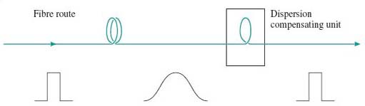
In particular, it is now possible to manufacture optical fibre with reversed dispersion characteristics. Thus, for example, if the refractive index of standard fibre is higher at 1551 nm than at 1550 nm, the dispersion compensating fibre has a refractive index that is lower at 1551 nm than at 1550 nm. Dispersion compensation is complicated to implement, but it allows existing fibre (standard single-mode fibre already installed) to be used with new systems. Furthermore, as will be seen later when we discuss fibre non-linearities, there are reasons why performance can be better over a system that uses dispersion compensation instead of zero-dispersion fibre.