

2.6 Connecting and splicing fibres
There are two different types of fibre joint that need to be considered: permanent splices (the equivalent of soldered or crimped connections on copper cables) and demountable connectors.
Splices are used along a route to allow a link to be built up from convenient lengths of cable. The lengths are typically 2 km. Fibre is manufactured in lengths longer than this, but, once put in a cable, lengths longer than 2 km are difficult to transport and lay. Splices are also used to repair breaks in fibres. Connectors are used at the interface of equipment (such as a repeater, amplifier or terminal) to the cable.
The basic aim of a fibre joint (splice or connector) is to allow light to pass from the core of one fibre to another, with as little loss or reflection as possible. This is made more difficult by the difficulty of aligning the two fibres accurately, given the small size of the core.
There are two classes of problem which lead to loss through a joint (referred to as insertion loss):
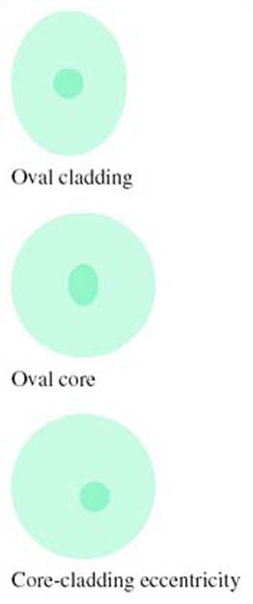
Those resulting from differences between two fibres being joined, possibly because of imperfections in the fibres (variations in core or cladding refractive indices, core or cladding diameters, ellipticity, eccentricity of core and cladding), see Figure 9.
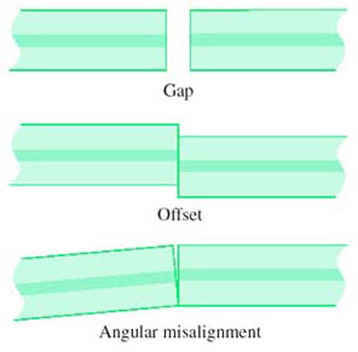
Those resulting from alignment error (gaps, offsets and angular misalignments of otherwise perfect fibres), see Figure 10. Because of the smaller core size, all of the above problems are more serious for single-mode than for multimode fibre.
It might seem that, since the critical feature of a joint is aligning the cores, features of the cladding such as ellipticity or different diameters are unimportant, but this is not generally so. Most joints rely on using the outside surface of the fibre for alignment, so errors in the cladding can be transferred to a core misalignment. A method of alignment which avoids this problem is discussed in the section on splicing below.
As well as insertion loss, reflections at connectors can be a problem. Any sort of discontinuity in a fibre can result in some light being reflected back towards the source, so most connectors cause some reflection. (Splices can also cause reflection, but usually to a lesser degree.) In particular, if there is a gap between the ends of the fibres the abrupt change in refractive index between the glass and the air in the gap causes a reflection referred to as Fresnel reflection. From optical theory it can be shown that a step change in refractive index from n1 to n2 causes a fraction, r, of the light power to be reflected, where r is given by:

The refractive index of fibre used in communications-grade optical fibre is around 1.5, and the refractive index of air is about 1.0, so the Fresnel reflection between the fibre and the air is:
So around 4% of the light power will be reflected when the light enters the air gap, and 96% will enter the gap, Figure 11.

Activity 9
How much light will be reflected when the light enters the fibre at the end of the air gap?
Answer
The same fraction is reflected on leaving the gap as entering: 4%. This is 4% of the 96% that entered the gap, which is 0.04 × 0.96 × 100 ≈ 3.8% of the original light power (see Figure 11).
Activity 10
What, in dB, is the total insertion loss due to the two reflections?
Answer
The light power getting through to the far side of the gap is 0.96 × 0.96 × 100 ≈ 92.2%. In dB this, the insertion loss, is given by −10 log 0.922 = 0.35 dB.
Activity 11
What, in dB, is the ratio between the incoming power and the reflected power (the return loss)?
Answer
The total reflected power is 4 + 3.8 = 7.8% of the original power, so the return loss in dB is −10 log 0.078 = 11.1 dB.
This calculation neglects light paths that involve more than one reflection. These losses will be very small. (The power after two reflections is 0.04 × 0.04 × 100 = 0.16%.)
Reflection will only occur in this way if the gap is much bigger than the wavelength of the light being conveyed. If the gap is much smaller than the wavelength there will be little or no reflection. If the gap is similar in size to the wavelength then the nature of the reflection is complicated by interference effects and the amount of reflection depends upon the precise dimensions.
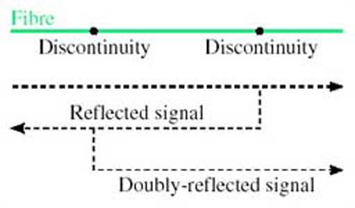
Reflected light can lead to increased noise on the signal from two effects. First, some lasers are sensitive to reflected light and become noisy or unstable when too much light is reflected back into them. Second, a double reflection (Figure 12) results in a delayed copy of the transmitted signal reaching the receiver. This delayed signal can result in an apparently disproportionately large amount of noise due to interference effects between the direct and reflected optical fields. Reflections are not normally a problem with splices, but techniques to minimise reflections have influenced changes in connector designs, as discussed influenced changes in connector designs, as discussed below.
SAQ 8
Suppose water intruded into the gap between two fibres. What fraction of power would be returned due to Fresnel reflections in that case? (Assume that the refractive index of water is 1.3.)
Answer
Using:
with n1 = 1.5 and n2 = 1.3 gives r = (0.2/2.8)2 = 0.0051, which is about 0.5%. This is the reflection from each surface (entering and leaving the gap), so the total reflection is about 1%.
The SAQ shows that the amount of reflection can be reduced by the presence in the gap of a material with refractive index close to that of glass. In practice water would not be used to do this – it would evaporate, for one thing. There are circumstance, however, where a special fluid or gel is used in the gap, which is designed to have the same refractive index as the glass and does not evaporate. This is index-matching fluid or index-matching gel.