2.6.1 Connectors
Many techniques have been used to design connectors that align the fibre ends accurately with high reliability and a long lifetime. The development of such components, at a low enough price, has been an important part of the overall development which has made fibre a feasible proposition for commercial transmission systems.
With fibre attenuation down to 0.2 dB km−1 (for single-mode fibre), the losses resulting from connectors and splices can be very significant over a whole route.
Activity 12
What length of fibre would have the same loss as the insertion loss due to the Fresnel reflections (0.35 dB) in a connector containing an air gap?
Answer
At 0.2 dB km−1, the loss due to the two Fresnel reflections in the connector is equivalent to 0.35/0.2 = 1.75 km of fibre.
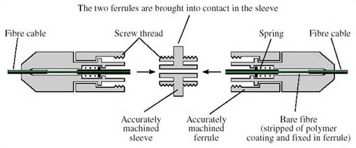
Figure 13 illustrates one type of connector, known as a ferrule connector (or FC connector).

In the basic connector the ends of the fibre are polished flat. In principle the two fibre ends could then abut, but any roughness on the surface (Figure 14), any dust on the fibre ends or any slight angular misalignment (Figure 10) will leave a gap between the cores. As noted above, if the gap is much less than the wavelength of the light being conveyed there is no problem, but since the wavelength is around 1.3 μm, this is a difficult target to meet.

Instead of polishing the ends flat, therefore, the ‘PC’ (physical contact) ferrule connector has the ends of the fibres polished to give two convex surfaces, resulting in better contact for the cores (Figure 15).

Even with the PC arrangement there is generally some residual reflection, and to minimise the reflections even further there is the angle-polished convex (APC) finish (Figure 16). (APC is sometimes taken to mean angled physical contact, but it still refers to the same method.) In this case the end-faces are polished at an angle, so that most of any light that is reflected is at an angle that is not guided by the fibre.

In general terms, PC connectors have the lowest insertion loss, whereas APC connectors have the lowest back reflections (APC is sometimes taken to mean angled physical contact, but it still refers to the same method.)
