
3.2 Directional couplers
A simple yet valuable device is the directional coupler (Figure 19). A directional coupler can be constructed from two single-mode fibres by bringing them into close contact and heating so that the glass melts and the two fibres fuse. Light can then pass from one fibre to the other.
A directional coupler constructed from fibres in this way is known as a fused fibre coupler.
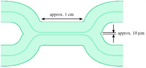
Depending upon the details of the way directional couplers are made – how long the fused section is, how closely joined the fibres are – they can be made to have different properties for different purposes. For example, a ‘3 dB coupler’ is designed so that light entering from one fibre splits equally to the two fibres at the output.
Activity 13
Why do you think this is called a 3 dB coupler? Think about the ratio between the input and output power.
Answer
Since the input is split equally between the two outputs, the power on each of the outputs is half that at the input (assuming an ideal device). In decibels, the ratio between the input power and the output power is therefore 10 log(2) = 3 dB.
The question assumed an ideal component. Real optical components invariably have additional loss due to imperfections. This is called the excess loss. The overall ratio between the input and output power, expressed in decibels, is the insertion loss.
Another factor that might need to be considered in a real 3 dB coupler is the asymmetry between the two outputs, because the splitting might not be exactly equal between the two.
Activity 14
Suppose a nominally 3 dB coupler has an excess loss of 0.1 dB. What is its insertion loss?
Answer
The insertion loss is just the nominal loss plus the excess loss, 3.1 dB.
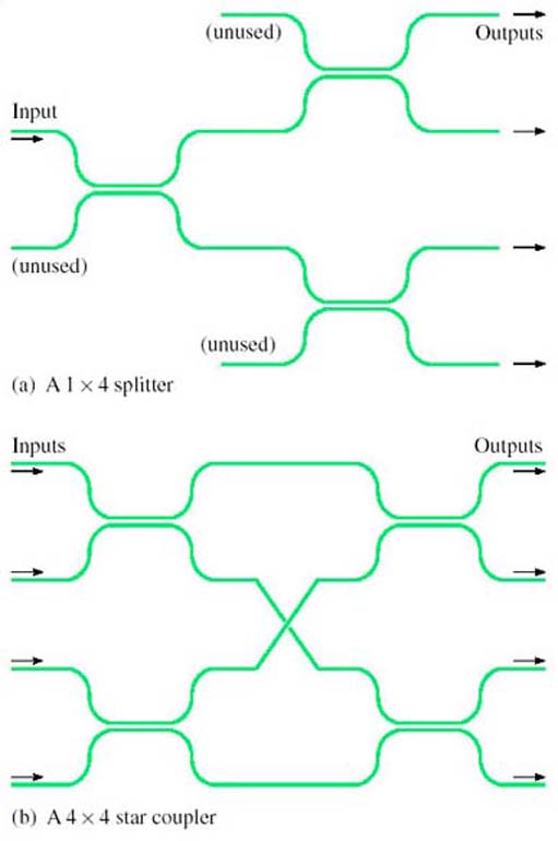
For some applications multi-way tree and star topologies are useful in fibre systems. Multi-way splitters and combiners (for the tree topology) and star couplers can be built from concatenated directional couplers as shown in Figure 20. Assuming the directional couplers are 3 dB couplers, the configuration in Figure 20(a) splits light equally to each of the four outputs. In the configuration in Figure 20(b) light on each of the four inputs is split equally to all of the four outputs – so the outputs each have light from all of the four inputs. Directional couplers work in both directions; so, for example, the splitter can also be used as a combiner. In Figure 20(a) one-quarter of the light entering any of the ‘outputs’ will reach the input. (It is only one-quarter, because the rest of the light goes to the fibres labelled ‘unused’.)
SAQ 9
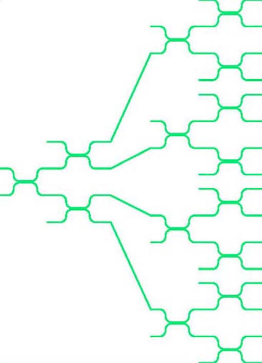
Suppose a splitter is built from 3 dB couplers to distribute light to 16 outputs, and that each of the couplers has an excess loss of 0.2 dB. If the power on the input is −4 dBm, what is the power on each of the outputs expressed both in dBm and milliwatts?
Answer
Each coupler introduces a loss of 3.2 dB. The light has to pass through four couplers to get to an output (see Figure 21), so the loss is
4 × 3.2 = 12.8 dB
The power on the output is therefore
−4 − 12.8 = −16.8 dBm
This is 10−1.68 = 0.0209 mW, or about 21 μW.
As a check that this is about right, the power on the input is −4 dBm which is 10−0.4 = 0.4 mW. If the splitters were perfect this would be split equally 16 ways, so that the power on each output would be 0.4/16 = 0.025 mW. The excess loss reduces this to 0.021 mW.
In general, the properties of a directional coupler depend upon wavelength, and this can be useful. For example, a device can be constructed to combine or split two wavelengths, to perform wavelength division multiplexing.