

2.4.1 Calculating the total heat loss of a house
If we know the U-values of all the elements of the external fabric of a building, its volume and its average ventilation rate, then we can calculate its overall heat loss coefficient (or heat transfer coefficient). We can define this as the total space heating energy flow rate in watts divided by the temperature difference between the inside and outside air.
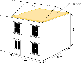
Let us take a reasonably modern end-of-terrace house insulated to standards suggested in the 2002 Building Regulations for England and Wales. Its dimensions are shown in Figure 21 and its total floor area (upstairs and downstairs) is 96 m2.
The total fabric heat loss flow rate, Qf, will be the sum of all the U-values of the individual elements of the external fabric, walls, roof, floor, windows and doors multiplied by their respective areas multiplied by the inside–outside temperature difference, ΔT.
- Qf = (ΣUxAx ) × ΔT watts - (note: the Σ symbol means ‘sum of’)
The total fabric contribution to the overall heat loss coefficient is then:
- Qf/ ΔT = ΣUxAx W K−1
This is calculated in Table 7.
| Element | Area / m2 |
U-value / W m–2 K–1 |
Contribution to heat loss coefficient /W K–1 |
|---|---|---|---|
| Floor | 48 | 0.25 | 48 × 0.25 = 12 |
| Roof | 48 | 0.16 | 48 × 0.16 = 7.7 |
| Walls | 80 | 0.35 | 80 × 0.35 = 28 |
| Windows and doors | 20 | 2.00 | 20 × 2.00 = 40 |
| Total | 87.7 |
Note that we assume that the adjacent house will be at the same internal temperature, so that there will be no heat loss through the (uninsulated) party wall between them. Also, in practice there will be extra conduction heat losses called ‘cold bridges’ through items such as pipework running through walls and the metal lintels over windows, but we will ignore these here.
We must also include the ventilation heat loss, which is:
- Qv = 0.33 × n × V × ΔT watts
where n is the number of air changes per hour (ACH) and V is the volume of the house (m3).
The ventilation contribution to the overall heat loss coefficient is then:
- Qv / ΔT = 0.33 × n × V W K−1
Assuming an air change rate of 0.5 ACH (which requires reasonably airtight construction) and taking the volume of the house as 240 m3:
- Qv / ΔT = 0.33 × 0.5 × 240 = 39.6 W K–1
Summing the fabric and ventilation contributions gives a total whole-house heat loss coefficient of:
- (Qf + Qv)/ΔT = 87.7 + 39.6 = 127.3 W K–1
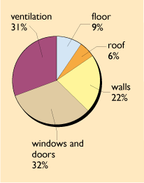
Figure 22 gives the percentage breakdown of these losses, which shows their relative importance and gives a clue as to where to look for further improvements.
We can use this whole house heat loss coefficient to estimate a suitable size for the heating system. If we assume an internal temperature of 20°C and site the house in London, for example, which has a winter design external temperature of –2°C, then the heating system must be able to maintain a temperature difference of 22 K. An estimate of the necessary heating system size, Qh, would thus be:
- Qh = 22 × 127.3 = 2800 W
In practice there is always an extra allowance to cope with warming up a house if it has been left empty for a few days.
If the house were situated in Berlin, which has much colder weather and a design temperature of –11°C, then the heating system would have to maintain a worst-case temperature difference of 31°C and would have to be rated at 31 × 127.3 = 3950 W.
Obviously the more insulation and the better the airtightness, the smaller (and hopefully cheaper) the heating system can be.