Software development for enterprise systems
Use 'Print preview' to check the number of pages and printer settings.
Print functionality varies between browsers.
Printable page generated Friday, 19 April 2024, 6:42 PM
Software development for enterprise systems
Introduction
Enterprise systems are software applications that automate and integrate all many of the key business processes of an organisation. With some understanding of software development, you will learn about current development practices for this type of system and develop relevant skills to apply them to real-world problems. You will develop core skills in object-oriented analysis and design, allowing you to develop software that is fit for purpose, reusable and amenable to change.
This OpenLearn course provides a sample of postgraduate study in Computing and ICT.
Learning outcomes
After studying this course, you should be able to:
describe a software development process used in an object-oriented approach to software
describe the activities that take place during software development
understand the different modelling perspectives used in the course, and what is important in each of them
understand the terminology of objects
understand the terms framework, component and pattern, and discuss their relevance to the development of more flexible software.
1. Introducing the terminology
Constructing enterprise systems is a complex engineering endeavour. As with other types of engineering, e.g. the construction of aircraft or suspension bridges, a lot of effort has to be put into planning and modelling, so that the final product is what is required and is achieved on time and within budget.
Ben Kovitz (1999) makes a distinction between orderly and exploratory. Orderly engineering is characterised primarily by the application and slight variation of time-tested techniques, design patterns and solutions but this does not mean that existing design and solutions can be routinely applied to solve new problems. Combining existing designs is a highly skilled activity that will always require some degree of imagination and ingenuity. Exploratory engineering is characterised primarily by the unstructured exploration of new kinds of techniques and design.
This course focuses on orderly engineering for enterprise systems. In particular, you will learn about current development practices for this type of system and develop relevant skills to apply them to real-world problems.
First of all, you will learn about the software development process, and its role in mitigating development risks. We use the term ‘development process’ to refer to the set of activities, methods, practices and transformations used to develop a piece of software (and associated products such as project plans and design documents).
The course also introduces you to the object-oriented approach to software. In particular, it will help you understand the concept of an object and related object technology concepts, such as encapsulation and inheritance.
Building models is an important activity throughout software development whatever approach is taken; models represent different aspects of the system and are built from different points of view. You will learn about the Unified Modeling Language (UML), a (primarily) diagrammatic language, to express models in an object-oriented approach. This course only contains a brief introduction to UML.
An important part of modelling is the ability to produce precise descriptions. No matter how abstract or expressive your models are, it is important that they describe precisely some facts of interest. At times, the need for precision will require the use of a more precise language. The Object Constraint Language (OCL) is a textual modelling language that is part of the UML. We will introduce it as needed to support UML models.
Realistic software development cannot be achieved without some tool support. In this course you will learn about a category of software tools, Computer Assisted Software Engineering (CASE) tools, which may help software developers to construct, document and track the evolution of artefacts during the development process.
Software is now a major factor in any business. Delivering software that meets your customer's need is of paramount importance. However, changes in business occur frequently, so software has to adapt to these frequent changes in order to keep a business competitive. Software development does not always mean development from scratch. Timely delivery of new software may mean that existing software has to be reused. You will learn about reuse of expertise, design and even existing systems or parts of them within new developed software.
The goal of this course is to introduce core skills in object-oriented analysis and design. Mastering such skills will enable you to develop software that is fit for purpose reusable and amenable to change.
Naturally, the course does not address the whole range of activities and skills that are required for successful software development. Many more skills are involved in, say eliciting requirements or designing usable interfaces or databases. This course only provides one piece in a much larger picture.
While this course is of an introductory nature, it will also expose you to current thinking in software development. It assumes you have some understanding of software development, but not necessarily any prior knowledge of the object-oriented approach, its principles and techniques.
Section 2 of this course describes some well-known software development processes. Models are used to represent the essential features of a situation and Section 3 introduces you to the different types of models you will encounter on the course, and to the languages used to express these models, UML and OCL. Section 4 describes the main concepts of an object-oriented approach. Reuse is described in Section 5 and the course ends with an introduction to CASE tools in Section 6.
2 Software development processes
2.1 Stakeholders and activities
Current enterprise systems are large and complex, and their construction involves many stakeholders, including customers, developers and users. Software development processes have emerged over the years to harness the complexity of software construction. A software development process describes an approach to building, deploying and maintaining software (Larman, 2002).
The advantages of following a well-understood process are many. From a manager's viewpoint, it is crucial to have well-defined activities that make it possible to estimate when a final product will be completed and the effort required to achieve it. From developer's viewpoint it is important to have well-defined tasks and clear outcomes, and to know which documents and artefacts should be produced by each of the activities undertaken. From a customer's viewpoint it is fundamental to be reassured that the required product is the one being built and that it will be delivered on time and within budget.
Software development processes vary in the details of the activities they prescribe, the related artefacts, and the software life cycle, i.e. how the activities should be carried out in relation to one another, and how often each activity should be revisited. There are some fundamental development activities that are common to most processes. These are: analysis, design, implementation, and testing.
In very general terms, analysis deals with understanding the problem and what is required of the system to be developed (the requirements); design deals with describing conceptually a software solution that meets the requirements of the problem; implementation builds such a solution; and testing helps to verify and validate it.
Verification is the set of activities that ensures that the software correctly implements a specific function (‘Are we building the product right?’) while validation is the set of activities that ensures that the software developed is traceable to the customer's requirements (‘Are we building the right product’).
Exercise 1
Which of the activities of analysis, design, implementation, and testing involve the participation of customers?
Answer
Solution
Customers will have to be involved mainly during analysis, to discuss the requirement for the system; they should also be involved later in validating and testing the software. However, in a process with short development cycles and frequent iterations, as you will see later, customers have a closer involvement with the whole of the development process.
2.2 From waterfall to iterative development
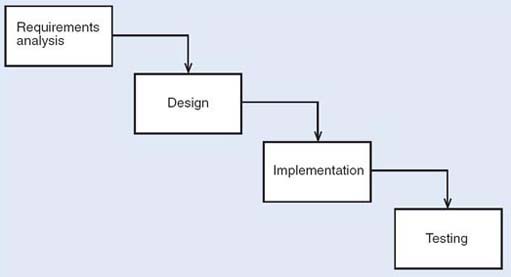
Historically, the first widely adopted software development process was the waterfall development process (or simply, waterfall).
The waterfall process relies on the definition of sequential phases, as shown in Figure 1. Each phase starts only after the previous one has finished; all the analysis is done first, followed by all the design, then the implementation, and finally the testing.
The waterfall process has been widely used and has produced many successful software products. However, it makes several assumptions that have been criticised.
For example, it relies on the existence of a set of requirements that is defined beforehand and remains unchanged during development; it also assumes that all code is designed from scratch, making no allowance for the reuse of existing software. Because the development is carried out as a linear process, the waterfall process does not allow previous phases of the development to be repeated without repeating the whole sequence of steps.
Exercise 2
-
What are the disadvantages of developing software in strict sequence through all its development phases?
-
Can you think of an advantage, from a management point of view, of developing the software in strict sequence?
Answer
Solution
-
The results of implementation and testing may lead to refinements in the requirements specification that are difficult to accommodate in a strictly sequentia development. The period of development is long, any feedback on the requirement comes too late, and the requirements may then no longer be valid.
-
The development process can be easily controlled, and it is easy to know when each phase has been completed, and to estimate the total length of the project.
The waterfall process is an important approach which has been widely applied in the past. However, its rigidity in the face of changes and its lack of support for reuse make it unsuitable for modern enterprise systems development, where coping with continuous business changes and short time-to-market is paramount. The inevitability of revisiting requirements to address problems identified earlier rather than later has led to processes that allow for a repetition of early phases before the end of development.
Iterative and incremental processes represent best practice that has been identified from the limitations of the waterfall process. The term ‘iterative’ indicates the repetition of one or more activities; the term ‘incremental’ indicates that development proceeds from an initial subset of the requirements to more and more complete subsets, until the whole system is addressed. Incremental development involves an initial partition of the intended functionality; some or all of the subsequent development activities can be carried out independently and in parallel. The final product results from the total integration of the partitions.
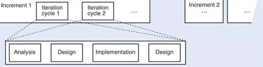
In iterative and incremental processes there is still a need for analysis, design, implementation and testing activities, but these activities are carried out in a more flexible way than in the waterfall process. An iterative and incremental process consists of several cycles of analysis, design, implementation and testing. Each cycle is short and provides feedback for the next cycle, in which a more refined and enhanced development is achieved. With an incremental model, development starts from small subsets of the requirements, reducing the complexity and scope of each analysis, design and coding cycle. Each increment is carried through the development activities to produce a working subset of the system, and is developed through several iterations. The integration of the increments results in the final system. However, this integration can be progressively achieved by successive releases of the software, each release achieving more functionality. Figure 2 illustrates an iterative and incremental model The increments represent development that can be carried out independently and in parallel. It should be stressed that the activities within each iteration are not necessarily sequential. Testing, for example, is no longer an activity that takes place only after implementation has terminated; tests start being developed as early as the analysis stage.
As each cycle deals with a small set of requirements, the complexity of each increment is managed; the complexity of the whole system needs to be managed by progressive integration of increments. Early feedback is obtained from a partial implementation. This implementation can be assessed early and may lead to alterations to some requirements or the completion of others. Reuse is also encouraged by partitioning the initial set of requirements, because it will be easier to identify reusable components that match requirements within each such partitioning.
Exercise 3
-
Why is early feedback, provided by each iteration, an advantage?
-
Can you think of any disadvantages that may be associated with an iterative and incremental development cycle?
Answer
Solution
-
It allows development effort that is going down a blind alley to be detected and halted.
-
It is difficult to know when to stop iterating; the integration of the partitions requires very careful definition of the interaction between these partitions.
2.3 Risk management
No software development is free from risk, and one crucial activity of development is identifying and managing it. Managing risks requires an early identification of any threats to the development or operation of a system, and then monitoring these threats during development. In an iterative and incremental development, risks in the development stage can be tightly monitored and controlled. The emphasis on short cycles that lead to early implementation helps to address technological problems from the start. The planning and prioritising of increments is done taking into account the risks that may occur (Fowler, 1997). Unforeseen problems can also be avoided by starting the integration of increments early.
Risks are mainly associated with making decisions that may be wrong and with misunderstanding requirements. There are different ways of classifying risks, according to different authors. Fowler, for example, classifies risks as requirements risks, technological risks, skills risks and political risks.
Exercise 4
Think of examples of each category of risk given by Fowler.
Answer
Solution
-
Requirements risks: building the wrong system, or one that does not satisfy the customer.
-
Technological risks: using the wrong tools to solve the problem.
-
Skills risks: not being able to gather the required expertise to develop the system.
-
Political risks: not recognising influential forces that may affect the development of the system.
The techniques you will learn in this course will help you deal with requirements and technological risks. Requirements risks may be minimised if the development cycles are short and restricted to a partition of the system. This allows decisions to be reconsidered and requirements to be improved and more clearly defined. The order in which increments are developed depends on their importance and on risk factors associated with them. Technological risks may be minimised by the use of the right tools; teaching you how to select and use these tools is one of the aims of this course.
3 The Unified Process
The Unified Process (UP) (Jacobson et al., 1999) has emerged as a popular iterative and incremental development process for building enterprise systems based on an object-oriented approach. It promotes a set of best practices, namely that development should be organised in short time-boxed iterations, and that it should be adaptive to accommodate inevitable change.
Time boxing means that a (usually) short fixed period of time is devoted to each iteration, e.g. three to four weeks. Consequently, only a small set of requirements is considered at each iteration and progressed to the implementation and testing stages Each iteration results in an executable, but incomplete system. Typically, many iterations and progressive integration of increments are required before the product can be delivered.
Adaptive means that adjustments are allowed at each iteration. The motivation for this is the recognition that requirements may change throughout development, and that such changes should be dealt with rather than resisted. By involving customers and users at each iteration, feedback can be gained quickly, and the required adjustments made within the next iteration. Hence, each iteration may provide an increment over, or simply revisit the output of, the previous one.
Other best practices promoted by UP are:
-
dealing with high-risk issues in early iterations;
-
giving the users' perspective great importance in the process and involving them in the definition of requirements, evaluation and feedback;
-
building a view of the system's architecture in early iterations.
A UP project is organised into four major phases:
-
Inception – this is where the business case is developed, together with an idea of the scope of the system and a rough estimate of the effort required.
-
Elaboration – this is where the core of the system is developed in an iterative fashion. In this phase, all major risks are addressed and resolved; most of the requirements are identified and dealt with; and a more realistic estimate of the effort required is made.
-
Construction – this is where the remaining lower risk and easier elements of the system are constructed, again in an iterative fashion.
-
Transition – this includes beta testing and deploying the system.
Within the UP phases, development work is organised within many disciplines. ‘Discipline’ is the UP term for development activities such as requirements analysis and testing. An example of disciplines and their relation to UP phases is given in Figure 3. (A detailed analysis of all of the disciplines here is outside the scope of this course.)
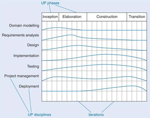
The figure is only illustrative of what a UP project would look like. The columns represent iterations. For each discipline, the relative effort is represented throughout the UP phases and their iterations. For instance, most of the domain modelling occurs in the early iterations of the inception and elaboration phases, while most of the implementation occurs within the construction phase.
This course is loosely based on the UP, with a focus on the elaboration phase and the disciplines of domain modelling (often referred to as business modelling), requirements analysis and design, and to some extent implementation and testing.
The techniques you will learn are not specific to the UP, though. In fact, they can be used in many iterative and incremental processes based on an object-oriented approach to software.
Exercise 5
Explain why the UP is not just a waterfall process in disguise.
Answer
Solution
Superficially, it would be possible to superimpose the waterfall life cycle onto the UP by identifying inception with requirements analysis, elaboration with design, and construction with implementation and testing.
This would be a misrepresentation of the UP for many reasons. In the UP you do not try to define most of the requirements before starting design, or to define most of the design before starting implementation. Instead, a small set of requirements is considered at each iteration and this small set is the focus of analysis, design and implementation. Thus, the system is developed incrementally, over many short iterations.
Also, the full project is not planned in detail from start to finish. An initial estimate is made and refined throughout the elaboration phase. This allows for the flexibility required in coping with requirements changes. This does not mean, however, that arbitrary changes can occur at any time in the project. The development plan must allow for all major risks to be addressed in early iterations in order to construct a stable system core for the remaining development.
4 Emergent approaches to software development
Iterative and incremental methods have been widely adopted in software development. Nowadays, high competitiveness, reduced time-to-market and pressure to develop flexible enterprise software together with the rapid change of technology have led to the emergence of new approaches to building, deploying and maintaining software. At the time of writing (2005), several new approaches to software development have been established that may become significant during the lifetime of this course. These include Model Driven Architecture (MDA) (see http://www.omg.org/mda/) and agile development (see http://agilemanifesto.org/).
MDA defines an approach whereby business-oriented decisions and specifications can be separated from implementation and platform (technology) decisions. The idea is to distinguish between platform independent models (PIMs) specified using UML, and platform specific models (PSMs) which carry relevant information for the generation of platform-specific code. Standard mappings between PIMs and PSMs should allow tools to be developed to automate some of the implementation. This approach is based on strong emphasis on:
-
models specified in a well-defined notation;
-
transformations between models;
-
formal underpinning of models and transformations;
-
industry adopted standards and tools.
Agile development (Cockburn and Highsmith, 2001; Fowler and Highsmith, 2001) is an umbrella term used to describe a variety of (agile) methods that encourage continual realignment of development goals with the needs and expectations of the customer. It represents a compromise between no process and too much process; a lighter weight, faster and nimbler software development process that can adapt to the inevitable changes in customer requirements.
The Agile Manifesto lists the following four principles:
Individuals and interactions over processes and tool
Working software over comprehensive documentation
Customer collaboration over contract negotiation
Responding to change over following a plan
(http://www.agilemanifesto.org, accessed 9 March 2005)
Extreme Programming (XP) (Beck, 2000) is one of the best known agile methods; it is very lightweight method, based on intensive testing and incremental development. It defines a series of practices such as small releases, simple design, testing, programming in pairs, collective ownership, continuous integration, 40-hour week, on-site customer, and coding standards.
5 Modelling and the UML
5.1 Domain, specification and design modelling
Building quality software is often a complex and lengthy task. Software developers build models that represent what is important, devoid of unnecessary detail. These models help them to deal with the complexity and to understand what is being developed.
This is not unlike other forms of design. For instance, when an architect develops model of a house as a set of drawings they will probably show where the walls and windows are and their relative sizes, but not any details about the materials used. The same happens when modelling software; with software, a model is an abstract representation of some view of a system. The view of a system changes with the stage of the development process. So, we have models with different perspectives according to the stage of development; we call them domain, specification and design models.
Domain modelling is concerned with understanding and modelling a situation independently of a decision to use a software system to deal with it. A domain model is a representation of the main concepts in the real-world problem, i.e. the business under consideration. A domain model does not assume that software is to be used to deal with the situation.
Specification modelling assumes that a software system will deal with a situation; a specification model represents software elements used in the software solution to problem, and is mainly concerned with the definition, at a high level of abstraction, of the services provided by the software.
Design modelling describes the software system, the allocation of responsibilities and the internal sequencing and control flow.
The distinction between domain and design models was introduced by Cook and Daniels (1994). They called the domain model the essential model, and the design model, the implementation model. Business model is also often used in the literature with a meaning similar to domain model.
You may wonder why we need to consider domain modelling at all. It is important to understand the domain fully, including the business, its resources and processes before suggesting any software product for that domain. The term ‘business’ is used in a wide sense to mean the situation in the enterprise that is relevant to the customer; it might be a commercial business, such as retailing, or a security alarm system. In any case, the important elements, whether they are people, products, departments, sensors, alarms or operators, need to be identified. Only by understanding the situation, and how, why and with what consequences it changes, can a software solution that is suitable for the enterprise be specified.
Domain and specification modelling may produce very similar models, but the interpretations of the models are different; the former are about real-world entities, the latter are about software representations of those entities. Modelling the domain will not always be necessary – for instance, when there is an accepted need for a well-defined software system to solve a well-understood situation. In this case, modelling the domain would not bring much advantage.
You may also wonder what the relation is between these three perspectives and the traditional split between analysis and design. In a simple way we could consider domain modelling and specification modelling as the analysis activities – that is, concerned with understanding what a problem is, and specifying what is required of the software system to be developed. In this course, however, we keep the distinction between domain modelling and specification modelling and use the term analysis for the latter As you might expect, design modelling corresponds to the design activity.
Exercise 6
-
Briefly describe when each of the three modelling perspectives (domain, specification and design) is relevant.
-
Can you think of a situation in which modelling the domain may not be necessary?
Answer
Solution
-
Domain modelling is relevant when we want to understand the business before any software development starts. Specification modelling is relevant when we have defined set of requirements and want to model what the system is going to do. Design modelling is relevant when we want to describe in detail how the software is to achieve the required behaviour; this involves, for example, representing the flow of control for the required functionality.
-
When the domain is well understood and the scope and boundary of a software system are well defined, modelling the domain may not be necessary, and development may start by specifying the software system. This is the case when the requirements are clear and unambiguous (such as building a text processor), but regrettably this is not often the case.
5.2 Modelling techniques and language
Models are built using techniques. A technique is a tool to describe a particular way of viewing and understanding a system. It guides the creation of a model and defines the notation used to create it. This can be narrative or diagrams or even mathematics. Techniques deal with the complexity of a system, abstracting essential aspects and representing them as models.
A modelling language defines the notations used for many different techniques. The Unified Modeling Language (UML) is the modelling language we will use in this course. It is one of the most popular and successful standards currently adopted by the software industry.
UML is the result of the merging of several object-oriented notations that appeared during the 1980s and early 1990s. As such, it is a big language, including many techniques, and even a mechanism to extend the notation. Here you will not learn UML in its entirety, but concentrate on a subset of the most commonly adopted techniques.
UML, being predominantly a diagrammatic language, cannot always precisely specify the complete semantics of a system and at times must be complemented by the use of natural language, say English, or by a textual modelling language, the Object Constraint Language (OCL). In this course, you will learn to express constraints on UML model precisely using English and OCL.
One thing that should be clear is that UML is a modelling language, not a development process; it gives you a set of notations, but it does not prescribe how these notations are to be used. In fact, because UML is the result of an exercise of unification, it can be used with many different processes: it is up to the development process to define how it should be used.
Some UML history
Many object-oriented methods appeared in the early 1990s and with them proliferation of techniques and notations. By the mid-1990s two authors of well-known methods (James Rumbaugh, one of the authors of OMT (object modelling technique, a predecessor of UML), and Grady Booch, author of the Booch method) (Rumbaugh et al., 1991; Booch, 1994) joined forces in an attempt to unify their methods; they named this effort the Unified Method. They were soon joined by Ivar Jacobson et al. (1992) (authors of OOSE) in the development of what became known as the Unified Modeling Language (UML). UML has evolved incorporating feedback from the object community, and it has received the support of many people and organisations which considered the idea of a unified modelling language a valuable one. UML was then submitted for standardisation to the Object Management Group (OMG), a consortium of several large software companies that produces and maintains computer industry specifications. UML was formally adopted in 1997. At the time of writing (2004), UML 2.0 specification is near completion and it is the basis of the notation we use in this course.
6 The object-oriented approach
6.1 Modularity and the object-oriented approach
In the previous sections we discussed software development processes and the role of modelling. In this section you will meet the main object concepts. Object-oriented programming preceded object-oriented development by many years, and it is where the object concepts originate. Once we have explained these concepts, we shall revisit software development and modelling in object terms.
One of the great successes of software engineering over the past 50 years has been the introduction of modularity in programming languages. The idea of breaking a sequential program into named pieces was developed in the late 1940s. Eventually whole design methods came to be based on structuring large pieces of software around their intended actions. Each action was broken into smaller actions, repeatedly, down to unit small enough to understand, write and test independently.
One advantage of structuring software around its basic actions is that it gives good traceability from the actions to the code. In a payroll system, the code associated with end-of-year reporting will be in a module with that name. Within that module, the code associated with the action of printing a report heading will be in a procedure with a name related to printing headings.
It is less easy to do the reverse. If, say, a system needs to be changed so that every time a date is printed it is shown with four digits for the year instead of two, there is no easy way to locate all the relevant bits of code, and, once they are located, thousands of lines may need to be modified.
It has been observed that as businesses change, the things their computer system manipulate stay fairly stable, although the ways they are used change rapidly.
Commercial systems will always need to represent taxes, goods, payments, prices and deliveries, even though the business rules determining who is creditworthy, how orders are taken, and whether payment is required before delivery may all change frequently.
This observation led to a desire to structure software around the things that were manipulated, rather than around the actions that manipulated them. There might be one unit of software that handled all operations on a ledger, another that did everything for payment, and another for an order. If a business were to change the way it works, it would probably still need these units but the way they are coupled would change. There might be greater reuse of software in other projects. All commercial projects include customers and ledgers, so these components may be reusable without change.
An object-oriented system is a software system whose basic structuring is around things rather than around actions.
6.2 Objects
To represent a thing such as an account or a payment from an object perspective, the software developers need to say how it can be used. An account is something that can be credited or debited with amounts of money and that remembers the total balance between operations. As users of an account, we do not care whether the balance is represented by electrons or by numbers on a slate, or whether the numbers are represented in binary or decimal. As long as we can withdraw money at some time after we have deposited it, it has all the behaviour of an account. An account must remember the current balance in some way, so it makes sense to talk about its state. Does it currently contain £100? How much would it have if we withdrew £27?
The usual way computers represent state is by storing values in variables. Behaviour is represented by operations of some sort. An object is a set of variables (data), with group of operations that can act on the data. But all programs contain operations and data, so what is the difference? The difference is the tight syntactic coupling between data and operations in an object-oriented language. In non-object systems, data tends to be globally accessible. Any part of a large program might access the main data store, such as a database or a data structure. There may be conventions and programming rules to suggest that accessing should be done in only a few places, but these are not enforceable. In an object system, the only operations that are allowed to access the data in an object are the operations attached to that object. Thus it is guaranteed that no other part of the system can touch the data.
To take a concrete example, think of how to represent dates. There are many candidate representations, such as:
-
a string with a month name and a two-digit year; for example, 2 March 97;
-
a string with slash-separated double-digit parts, with the month first; for example, 03/02/97;
-
three integers, with the year in the range 0–99; for example, 2, 3, 99;
-
an integer count of the number of days since 1 January 1901.
All these have advantages and disadvantages. Some are easier to print, others easier to parse, and others easier to compare to see which of two dates is the earlier.
If data is globally visible, a decision is usually made about the format, and that decision is published to the writers of every module that may need to use dates. Code is written according to the representation selected. For example, if the second representation is chosen, any code that needs the year will directly access the last two characters. Suppose it is necessary to change the format of dates, perhaps to speed up some operation that is done frequently, such as comparing, or to extend the range of representable dates. If the representation has been explicitly published, lots of code will depend on it, and changing it will be non-trivial. Every piece of code using a date will need to be altered.
If, instead, a date had been made into an object, no code outside the Date object could have manipulated the particular representation it used. All operations would be done by invoking operations of the Date object. When data are entirely hidden behind operations which alone can manipulate them, they are said to be encapsulated. Encapsulation is one of the central concepts of object-oriented technology.
Encapsulation provides an explicit boundary which separates information about which operations are available from information on how they are implemented. Outside the Date object, available operations are advertised via their signatures only (the signature of an operation is the specification of the type of the arguments and of the result of the operation); a signature specifies how an operation can be invoked. The implementation of the operations, i.e. how they access and modify data, is not visible outside the object. The visible operation signatures are said to be public while the encapsulated data and operation implementation are said to be private.
The operations provide all the information that anyone using a date would need. There is never a need to access the underlying representation of the date. If the representation needs to change, only the implementation of the operations on date need to be rewritten. All clients are totally unaffected, because they manipulate dates only through the operations provided. They need only to know the operation names – not their implementations – and the operation names stay the same whatever the representation.
Exercise 7
Explain encapsulation from an object-oriented perspective.
Answer
Solution
Encapsulation is the mechanism that allows objects to hide private implementation details while advertising their public interface. Typically, the public interface is collection of operations that can be invoked by other objects, while the private implementation is made up of data and code, which are used to carry out those operations.
6.3 Networks of objects
No serious program consists of a single object. Instead there will be a network of objects, which collaborate to achieve the functionality of the whole system. Figure 4 shows a network of objects representing a hotel, some guests and some rooms. This sort of diagram is called an object diagram or a snapshot diagram. It shows one particular possible configuration of the system. This particular diagram shows the state of the system when it contains a single hotel, two guests and two rooms. The guest with name ‘Jack’ is linked to the room with name ‘blue suite’, and the guest with name ‘Jill’ is linked to the room with name ‘r234’.
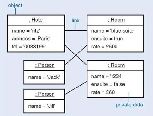
The notation used in Figure 4 is the UML notation for object diagrams. Each box represents an object and the data it encapsulates, and that objects can be linked to other objects.
A link is a connection between two objects that is significant for the application area. To establish a connection between two objects we need to identify, and distinguish between, each object. An identity is an unchanging property of an object that distinguishes it from all other objects. Software distinguishes between objects using an internal identity that is intelligible only to the software system; objects are not distinguished by the data they store.
How people distinguish between real-world objects is different from how software distinguishes between objects which may represent those real-world objects. People distinguish between real-world objects using identifiers with values that are understood by other people, e.g. a property such as a person's name. This conflict of identities has to be resolved by the interface between a system and its users.
6.4 Collaborating objects
The objects that comprise a program collaborate with one another to fulfill the functions of the system that the program represents. Collaboration occurs when one object requests a service from another object in order to perform some task. To fulfill a particular collaboration, each object takes on a different role. The object that makes the request is called the client, and the object that receives the request (and provides the service in response) is called the server. The request is communicated to the server from the client by message passing. The client sends a message to the server which on receipt executes the operation with the same name and signature as the message. When the server has completed the execution of its operation it returns a message answer to the client. Both the message and message answer may convey data between the objects The signature of the operation is the specification of the type of the arguments and of the result of the operation, e.g. create (name: String, rate: Money, ensuited: Boolean): Room. For brevity, parameter names can be omitted, e.g. create (String, Money, Boolean): Room.
Figure 5 shows the collaboration between Room and Person objects (from the hotel example in Figure 4) where the Room object requests that the Person object linked to it provides the value associated with its name attribute. The Room object, as the client, sends the getName message to the Person object which, as the server, executes the getName operation on receipt of the message. When the Person object has completed the execution of the getName operation it returns the value associated with its name attribute to the client as the message answer.
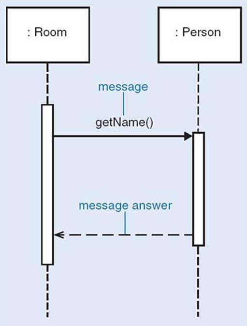
The notation used in Figure 5 is the UML notation for sequence diagrams. Each box represents an object.
For a client object to collaborate successfully with a server object, two conditions must be met:
-
the client must know the identity of the server (to be able to send messages to it);
-
the server must understand the message, i.e. it must have an operation with the same name and signature as the message.
Exercise 8
Consider a situation where an Account object provides a debit service by executing the operation debit with the signature debit(amount: Money), and a Bank object wants to debit an amount of 50 from that Account object. Identify the client, the server and the message in this collaboration.
Discussion
Solution
The Account object is the server, the Bank object is the client, the message is debit(50); there is no message answer as the debit operation does not return a value. (However, it will return the flow of control on completion of the operation.)
The public operations that are made available to clients are what matters in the use of an object, rather than any private data it may happen to store internally to represent its state. The set of public operations that can be executed by an object is called its protocol or interface. We shall use the terms interface and protocol interchangeably to refer to the set of behaviours or operations an object offers. An Account object is likely to have the following operations in its protocol: getBalance, debit, and credit.
By convention, when the name of an operation is made up of more than one word, the second and subsequent words have initial upper-case letters, e.g. getBalance.
6.5 Classes
In the hotel system, each room is different and may have a different occupant. However all rooms are the same in that each has a room name and a rate, for example, and each may have an occupant. If something did not have a room name and a rate, it would not count as a hotel room. Thus we generally talk about objects in terms of general classifications. Instead of repeatedly saying that the objects representing rooms 201 and 302 have names, can be ensuite or not and have a rate, we define the general properties of the Room class. In object terms, we say that rooms 201 and 302 are both instances of the class Room. We define a class called Room, saying what properties it has. Then by saying that rooms 201 and 302 are both instances of Room, we automatically understand that each has all the properties of the class.
System designers do not want to have to specify each room individually because all the rooms share a similar structure and behaviour; these shared properties can be captured once rather than repeatedly. So it is necessary to capture what all the rooms have in common, rather than the particulars of each separate room. Designing and programming in an object-oriented language consists mostly of writing definitions of classes, rather than of individual objects. One of the main challenges is to identify the properties that must be represented for any system.
It is useful to have a notation more abstract than program code to help us think about classes. A class diagram is one of the UML techniques previously mentioned, and we will be using it for this purpose. In a class diagram, each class is represented by a box called a class icon, divided into three areas, called compartments. The top compartment contains the class name, and the bottom one all the operations that are defined for that class. The name and the list of operations are all that clients of the class need to know. However, to implement the class, designers also need to know the structure of the class, so the middle compartment contains all the variables that constitute the current representation of the class; such variables are called attributes.
Figure 6 shows two class definitions. These represent all possible employees and all possible user interface windows within a system, respectively. The left-hand diagram shows the common structure of the Employee objects, indicating which operations can be applied to an Employee object and which data an Employee object stores. Each Employee object has exactly the same set of operations, but obviously each instance of Employee will have its own data. The data for the employee Jack are distinct from the data for employee Jill.
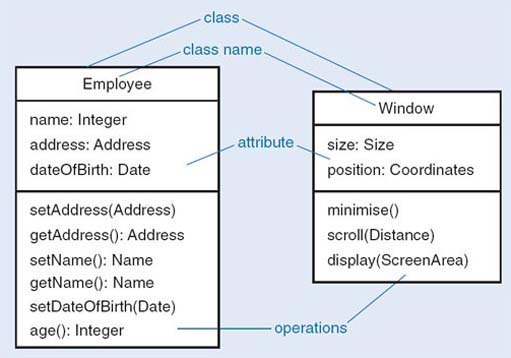
The class Employee has the operations setAddress and getAddress, setName and getName, setDateOfBirth and age. Only the name, address and date of birth are stored, so determining an age will require some computation. The representation might be changed later to store the age explicitly, but that would not affect any of the object's clients, because they use only the public operations, which would not have changed.
Exercise 9
What is the relationship between a class and an object?
Discussion
Solution
A class is a generalisation of all its instances, saying what structure and operations they have in common. Objects are the instances of a class.
6.6 Inheritance
When several different classes that support the same protocol are implemented, there could be a lot of repetitive coding. Rather than duplicate code in different classes, most object-oriented systems allow for the sharing of the implementation of operations, by mechanism called inheritance. Using inheritance, one class can be defined as basically similar to another, and just the ways in which they differ can be implemented. Indeed, in the early days of object-oriented design, the use of inheritance was called programming by difference.
Consider the classes and their respective operations, shown in Table 1.
| Account | SavingsAccount |
|---|---|
| credit(Money) | credit(Money) |
| debit(Money) | debit(Money) |
| balance(): Money | balance(): Money |
| addInterestTo(Date) | |
| dateOfLastInterest(): Date | |
| dateOfLastWithdrawal(): Date |
Clearly, there is some overlap between the two lists. Each class provides an operation called balance, which returns the current balance. It probably makes sense for both classes to implement this in the same way – say to store some private data representing the balance and return the current value. The code for the credit operations is probably identical, but the code for the debit operation is probably not identical, because SavingsAccount may have different restrictions for withdrawal. SavingsAccount also provides many operations that are special to saving accounts which ordinary account do not have.
Thus SavingsAccount is similar to Account but with a different implementation of debit and some extra operations. This is expressed in object-oriented languages by saying that SavingsAccount is A subclass of Account. A subclass (here SavingsAccount) inherits all the operations of the superclass (here Account), but it may add some extra ones, and it may override some of the inherited ones by providing definitions of its own. SavingsAccount has all the operations of Account, but it also has some extra ones, and it overrides the debit operation with a different implementation of its own. A subclass always has the whole protocol of its superclass.
The subclass is allowed to add extra operations, and to override existing operations of the superclass, but it is not allowed to remove operations. CurrentAccount could not be defined as SavingsAccount without the operations to do with handling interest. The reason for this becomes apparent if protocols are considered. The protocol of Account is (credit debit, balance). If subclasses are allowed to add operations, and redefine operations, the subclasses of Account will still support the same protocol. (They may also support other protocols, but that is not the issue here.) If both Account and SavingsAccount support a shared protocol, they can be used in the same way by other classes. For example, there might be a club which keeps its assets in an instance of Account. It could change to using SavingsAccount without needing to modify the club at all, because the club will be written to use the protocol of Account, and all subclasses of Account necessarily support the same protocol as Account. Figure 7 shows an inheritance tree for Account and SavingsAccount.
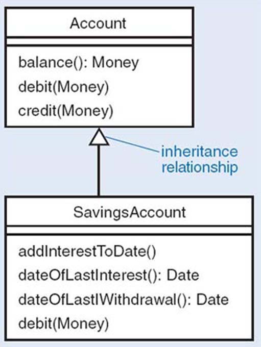
The open arrowheads between classes represent the inheritance relation, going from subclass to superclass. They could be verbalised as ‘is a kind of’ (or ‘is-a’).
One purpose of inheritance is to allow two different classes to share code. Sometimes this results in the creation of classes that do not represent anything in the problem. They are there simply to enable code to be shared. For example, in a word-processing application, there might be the classes Paragraph and Picture, in which several operations were identical. The cut, paste and copy operations might be identical, and so to save repetitive coding, both Paragraph and Picture could be made subclasses of new class, DocumentElement, and the shared operations put in that class. Such a class is called an abstract class. It is created solely for the purposes of sharing code between subclasses and there should never be any instances of DocumentElement.
Some object languages allow for multiple inheritance, in which a class is allowed to inherit from several superclasses. For instance, Car class might inherit both from Vehicle and from FinancialAsset. The merits and problems of multiple inheritance are much discussed among designers. Some languages, like Smalltalk or Java, do not implement multiple inheritance; they allow only a single superclass for any class.
Exercise 10
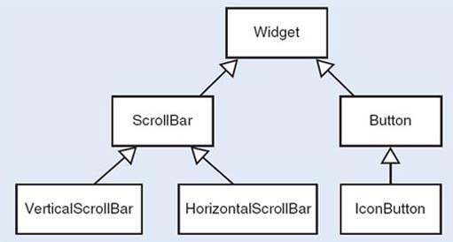
-
The components that make up a graphical user interface (GUI) are often called widgets. Arrange the classes VerticalScrollBar, Widget, Button, IconButton, ScrollBar, HorizontalScrollBar into an inheritance tree.
-
The class Transporter represents anything that transports people. Design two different inheritance trees to hold the classes Ferry, Dinghy, Car and Bus – one in which the most important distinction is between public and private transport, the other in which the primary division is between water and land transport. You will have to create some extra classes.
-
Arrange the classes Person, Doctor, Patient, Surgeon, Anaesthetist, InPatient and OutPatient into an inheritance tree.
Discussion
Solution
The following figures show some candidate trees.
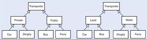
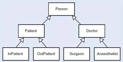
Observe that an object, once created, belongs to only one class and cannot change classes. In the medical example, if a world in which doctors may become patients, or out-patients may become in-patients were to be modelled, this would not be an appropriate representation. Whether or not an inheritance structure is appropriate depends entirely on what is to be done with the objects.
6.7 Modelling with objects
Object-oriented software development is very much focused on representing the world of the problem domain as a set of interacting objects. If the classes of the objects are chosen to correspond to natural categories of things in the world, such as customer invoice, payment, bill, there will be a structural similarity between the world and the software. This can lead to good traceability from requirements through to code.
Domain, analysis and design are the three modelling perspectives that will guide us from a real-world situation to a final software product to address the real-world situation or part of it.
In domain modelling we represent the main concepts of the real-world problem. In terms of object-oriented development, domain modelling corresponds to identifying the important objects in the situation and building models in terms of these objects and their interactions. Its purpose is to get a better understanding of the domain; this can be done as part of the elicitation of requirements or even when the requirements have been gathered but it is important from a developer's point of view to understand the business situation that those requirements address.
In analysis (we use this term for the specification modelling activities), we assume that software system is needed to address a situation. Here we model software elements used in a software solution to the problem but avoid too many implementation details. Object-oriented analysis models are built in terms of the software representation of the real-world objects. The main emphasis is on the services provided by the software solution and not on how these services are provided.
Design modelling describes the software system, the allocation of responsibilities, and the internal sequencing and control flow. In object terms, a design model represents the software classes and objects and the messages exchanged between them and in which order. The functionality of the entire system is distributed among the classes. For instance, in a hotel system, a decision must be taken on whether the code that does the check-in of a guest into the hotel and allocates a room should be part of the Hotel class or the Person class, or whether a special class called CheckerIn is needed. Depending on the decisions made, the end product will be flexible comprehensible software that is easy to change or a rigid mess which is as intractable as the worst of coded designs. Object technology (that is, software that is built following an object-oriented approach) is an enabler of good software structures, but does not of itself guarantee them.
In software development it is difficult to say where analysis stops and design starts. In object-oriented development this is particularly true, as the techniques used are virtually the same and, therefore, the transition from analysis to design is less pronounced. Although we do not want to impose a strict division between analysis and design, we will be using these terms with the following meanings:
-
Analysis is concerned with identifying the objects in the problem domain, their relationships and behaviour, and specifying their software representation only in terms of what a software system will have to achieve (and not how it will achieve it).
-
Design is concerned with design modelling; that is, the responsibilities of each class, the services the classes provide and their object collaborations to achieve the desired behaviour.
Exercise 11
You have seen what objects, classes, operations and attributes are in object-oriented terms. Imagine now that you are starting from an agreed statement of your customer's requirements. Which steps do you think would get you from this statement to working code?
Discussion
Solution
We would expect you to have come up with a list containing some of the following steps.
-
Consider the data requirements for a class.
-
Identify the classes, together with their attributes and operations.
-
Define a class hierarchy.
-
Design and program the operations.
-
Code the program in an object-oriented language.
7 Reuse
7.1 The advantages of reuseability
Reuse is the process of building new software from existing software assets, rather than starting from scratch. Reuse is an important factor in building flexible products that can be changed quickly in response to changes in requirements.
One of the advantages claimed of object technology is that it encourages a disciplined approach that facilitates reuse. Encapsulation encourages better designs that can be reused in a more reliable way, as there is exact knowledge of which operations access which data. It restricts the assumptions made of an object to a well-defined protocol. Inheritance allows a developer to reuse a class whose behaviour provides some of the behaviour required of the new class, so that only the different parts need to be designed.
Large-scale reuse, however, requires more than just discipline. It also demands mechanisms to describe the behaviour and interfaces of each replaceable part, and easy ways to connect such parts together. Originally, reuse in an object-oriented context was centred around the concept of class. In time, however, this perspective has widened, and other units of reuse have been defined. In the remainder of this section we will review some of them, including the concepts of framework, component and pattern.
Exercise 12
Which artefacts of a software development process can you identify as reusable?
Answer
Solution
Reuse in software development can happen at different levels: requirements, specifications, designs, code, tests, and documents are all examples of reusable artefacts.
7.2 Frameworks
A framework is a set of classes with well-defined interactions which are designed to solve specific problems. Frameworks are usually developed for a specific domain of application, say financial management or document preparation. They go some way towards a complete solution, but require some degree of customisation, usually through the creation of subclasses within the framework or by overriding operations. Coplien suggests:
A framework defines a subsystem or mechanism that is customizable. The subsystem design is encapsulated by a set of classes, though the implementation may only be partially defined. Framework abstract base classes leave some member function definitions to the application
(Coplien, 1995)
Many frameworks have been developed, and some are commercially available. For instance, the Smalltalk Model-View-Controller (MVC) is a well-known user interface framework, originally developed by Xerox PARC in the 1970s within the Smalltalk system. It was designed to support the creation of object-based, direct manipulation interfaces whose graphic interface widgets, such as windows, buttons and so on, could be reused in different applications. Many object-oriented languages today include libraries of reusable assets based on the same design principles of the Smalltalk MVC The Java Swing, a graphical user interface (GUI) library, is one such example.
One commonly encountered framework is called J2EE. J2EE is a trademark of Sun Microsystems Inc. In the literature it is also referred to as a component architecture, a reference architecture or a platform. It is a large collection of Java technologies and components that can be used to produce a wide variety of distributed information systems. J2EE has proved very successful and has become one of the most widely used frameworks for the development of client server applications. These are applications characterised by two distinct pieces of software: the client, which receives requests from the users of the systems, and the server, which processes such requests. Client and server are not usually co-located within the same computer, but distributed across a network. Web applications are well-known examples of client-server systems.
7.3 Components
The term component has been used since software engineering emerged as a discipline in 1968, and it reflects the analogy with other engineering disciplines. Like electronic devices that have pins and are connected with wires, software components are seen as independent software artefacts that can be used unchanged to build larger systems.
In most systems, it is usually easy to identify parts that are common to a number of applications. Each system may itself be considered a set of components collaborating to achieve the overall functionality. Ideally, systems could be built from components selected from a wide range, and connected or plugged together. The term Component-Based Development (CBD) (D'Souza and Wills, 1998) has been used for software developed by assembling existing components. CBD relies on the existence of libraries of components and on the publication of information about new components that can be used in other applications. It does not necessarily require object-oriented development, but the characteristics of object technology facilitate the development.
Mostly, it is not enough simply to connect components together; some extra code needs to be written to adapt their interfaces and guarantee that they can work together; this is usually called glue code. It is also accepted now that components, rather than being developed in isolation, should be developed within a framework for their application. The concept of product line (Clements and Northrop, 2002) is based on the idea that within a specific domain many different products can be developed with a similar structure and with well-identified variation points; these variations usually correspond to alternative components that can be plugged into the defined architecture.
Exercise 13
-
Explain the differences between a component and a framework. How can they be used? Give an example of each.
-
The development of a framework is a difficult task that should take into account the different ways it may be used. Describe what is involved in developing a framework from an existing set of similar applications.
Answer
Solution
-
A component is used unchanged; a framework has to be customised by creating subclasses of classes of the framework and/or writing specific operations for the specific application of the framework. A product line well exemplifies the distinction between a framework and a component. A product line architecture defines a framework and a set of components that can be used within this framework, but it also has modification and extension points that make it applicable to a wide range of applications.
-
When a framework is being developed, it is necessary to consider what may be common across different applications in the same domain and abstract (factor out) the commonality in the framework. This involves defining abstract classes that can be specialised and writing operations specifically for each application.
7.4 Patterns
While frameworks and components focus on the reuse of previously developed software, patterns focus on the reuse of expertise. A pattern is a general solution to problem; it is the result of abstracting what is common practice in solving a set of similar problems.
Patterns became a significant topic during the 1990s within an object community disappointed with the low level of reuse being achieved. Instead of concentrating on yet more new methods, the patterns movement looked at ways of building on the collective experience of solving frequent problems. There are many common and recurrent design problems for which good solutions exist and can be repeatedly applied. Design patterns capture such solutions in a way that can be applied generally. Moreover, by cataloguing problems and their solutions, patterns are a means to transfer expertise from the experienced to the novice software developer.
The patterns movement in software was inspired by a building architect, Christopher Alexander, who has written extensively on the use of design patterns for living and working spaces – homes, buildings, communal areas and towns (Alexander et al., 1977). According to Alexander, ‘each pattern describes a problem which occurs over and over again, in such a way that you can use this solution a million times over, without ever doing it the same way twice’.
Patterns became very popular following the publication of a catalogue of design patterns by a group of authors commonly known as the ‘Gang of Four’ (Gamma et al., 1995). Many more pattern catalogues have now been published, widening their original scope from design to most aspects of software development, including analysis and implementation.
Patterns from the literature have many different styles and serve many different purposes. Here is a brief overview of well-known pattern types.
Process patterns describe rules that can be followed when software systems are built, e.g. how to re-engineer an existing system with a pattern. In such a case the patter describes a strategy to follow. In 1997, Martin Fowler published a book on analysis patterns offering solutions to problems faced during business modelling, and in this case patterns describe general modelling issues. One analysis pattern presented by Fowler, for example, is called the Accountability Knowledge Level, and it indicates solution to deal with complexity in models by separating two types: a knowledge mode and an operational model. The Catalysis book (D'Souza et al., 1998) uses patterns to describe how the method proposed can be applied; each pattern presents a strategy for development. Fowler has also published (2002) another book on patterns for the design of enterprise systems architectures.
A design pattern is a set of classes and objects that solves a general design problem, and needs be customised for each specific context. A well-known design pattern from the ‘Gang of Four’ catalogue is the Observer pattern. It defines how to establish dependency between objects which guarantees that when one object changes state all its dependents are notified of that change. This pattern is implemented in many MVC-based interfaces and systems, in which a dependency mechanism exists between a set of domain objects (the model) and their visual representation (the views).
With most programming languages there is an accumulated knowledge of the experience of many programmers. Language patterns represent solutions to recurring programming problems within specific languages. Many language pattern catalogues exist; for instance, Kent Beck (1997) has written one on Smalltalk patterns, while Mark Grand (1998, 1999) has published two volumes on Java patterns. Such catalogues include patterns on how to access the variables of an object, how to name operations how to initialise objects. At the programming language level, language-specific patterns are usually known as idioms.
7.4.1 Architectural patterns
A software architecture is the broad structure of a software system. It describes its parts and how they are put together, and also captures an underlying rationale and associated concepts, such as professionalism (liability) and constraints (such as standards and economics). The term architecture is, again, reminiscent of its use in buildings.
Architectural patterns (also known as architectural styles) codify recurrent software architectures by describing the key elements of the architecture and how they fit together (Buschmann et al., 1996). They also describe the qualities of systems that are assembled following the pattern (Shaw and Garlan, 1996; Bass et al., 1998). For instance, the Pipe-and-Filter architectural pattern prescribes two types of components, the pipes and the filters, which are used to transfer and transform data, respectively Their connection must be such that filters can only be linked through pipes. The patter is suitable for systems whose main aim is to transform data from one format to another through incremental transformations. The resulting systems are simple to understand and maintain, and their components are highly reusable.
Patterns are not just descriptions of solutions; they also indicate how to identify problem and its context, which strategy should be followed, and the consequences of applying the pattern. There are many different templates to describe patterns which have been used by different authors; we will adopt the following, adapted from Fowler (2002).
-
Name: This is the name by which the pattern is referred to; it should be evocative of what the pattern is about in order to create a pattern language that encourages meaningful communication between developers.
-
Intent: This is a brief description of the purpose of the pattern.
-
How it works: This is a description of the solution; it should be implementation neutral, and may include some UML notation.
-
When to use it: This is a description of when the pattern should be used, possible relations to other patterns, and possible trade-offs.
-
Example: This may include examples of application of the pattern.
During the course you will have an opportunity to study several patterns, within various phases of software development.
Exercise 14
-
What makes the use of patterns different from applying a new development method?
-
What is the difference between a framework and a pattern?
Answer
Solution
-
Patterns concentrate on actual designs and on existing practical experience of solving problems; they represent previous experience. A pattern is not accepted if there are no existing examples of its use.
-
While a pattern is a general solution (a rule) to a specific problem, a framework is more concrete and part of the solution. A framework comes with code to be reused as it is, or to be extended for specific customisations. Frameworks are also usually for a specific application domain, while patterns can be used with many domains. Frameworks are usually larger, while patterns solve small problems and can be used within frameworks, but not the other way round. For instance, the Observer pattern deals with dependencies between a model and its presentation. The MVC user interface framework uses the Observer pattern as well as other patterns (from the ‘Gang of Four’ book). Patterns are used by following the suggested structure in the implementation; the framework classes are subclassed and application-specific methods implemented. Patterns are small architectural elements, while frameworks are partial or total solutions in an application domain.
8 CASE tools
Computer Assisted Software Engineering (CASE) tools were developed to support the professional system developer and improve their productivity in the complex task of developing large information systems.
The benefits that may accrue from the use of such tools are many. From a developer’s viewpoint, they provide support for modelling aspects of the system using a variety of notations and techniques: from diagrams to mathematics and text, producing prototype code, and even verifying the correctness of the system design. They also automate the sometimes tedious process of writing system documentation and keeping it up to date. They often allow the creation and management of a central repository of documents and other artefacts. This is useful both for communication within a development team, and for project management and decision tracking. Importantly, they improve the quality of the development processes by supporting, and to a large extent enforcing, a standard methodology and sound design principles.
Despite these potential benefits, there are often obstacles to their adoption. The introduction of a CASE tool within an organisation comes at a high cost: an upfront investment is required to acquire the technology and to train personnel accordingly, while the benefits of using the tool manifest themselves only in the long term. CASE tools are only effective if standard methodologies and processes are adopted across the organisation; the definition of standard procedures and practices also has to be established at the beginning. At times the obstacles are cultural: there may be some resistance from analysts and developers who perceive the rigidity of an enforced methodology as a threat to their autonomy and creativity. The initial learning curve is quite steep and they may not consider the effort worthwhile in terms of improvement in productivity and quality. Another major drawback is that the available tools tend to be narrow in their focus and concentrate on small subset of activities within the development process. For instance, most tools support modelling, while hardly any provide facilities for communication between customers and developers. This may result in a variety of tools to be used within a process, with all the difficulties arising from integration and interchange of information.
Exercise 15
Which factors may contribute to the successful adoption of CASE tools within a organisation?
Answer
Solution
There should be established methods and procedures across the organisation that can be supported by the tools.
Adequate investment should be put into training managers and developers.
Deployment should occur over a long period of time, as the benefits of CASE tools are not short term.
Clear procedures should be established for the use of different tools within development and standards should be followed for information exchange among tools.
To overcome some of the deficiencies of current tools, they should be integrated within practices that support project management and customer/developer communication.
A great variety of tools are available today, supporting many different functions within software development. Table 2 gives a brief taxonomy of tools based on their function; the list is not meant to be exhaustive. Also, many current CASE systems integrate many such functions within the same application environment.
| Tool | Function |
|---|---|
| Process management tools | To capture and model development processes |
| Project management tools | To plan and schedule projects, and track progress |
| Risk analysis tools | To record, categorise and analyse risks |
| Requirements management tools | To capture, analyse and trace requirements throughout development |
| Metrics tools | To capture specific software metrics and provide overall measures of quality |
| Modelling tools | To support modelling within analysis and design activities |
| Programming tools | To support code development |
| Interface design tools | To support the design of graphical use interfaces (GUI) |
| Test management tools | To manage and coordinate testing |
Particularly relevant to this course are UML modelling tools, which support the creation of models based on UML techniques. Many such tools are available, from simple diagrammatic tools to fully blown integrated environments with project management, document repository and code generation capabilities. You will have an opportunity to explore the capability of one such tool during the course.
Conclusion
This course has introduced the main concepts used in this course, has given an overview of software development with an object-oriented approach and has discussed some of the issues that are relevant to developing software that can be reused. Here are the main points addressed in the course.
-
An iterative and incremental model for the development process is more appropriate to object-oriented development than a traditional sequential waterfall model. Iteration cycles allow for the reviewing of previous steps, and partitioning into increments addresses complexity.
-
Modelling is carried out from three different perspectives. First, by modelling the domain to understand what a business does, independently of a software solution; modelling at this stage identifies the objects in the domain of the problem, their relations and their behaviours. Second, if a software solution is appropriate, modelling specifies the software objects, their relations and their behaviours; this is the software specification perspective. Third, design modelling is concerned with the distribution of responsibilities and the software control flow to achieve the required behaviour.
-
The concepts of object and class have been introduced, as well as the principal concepts in object technology: encapsulation and inheritance.
-
Reuse is a crucial factor in the adoption of object technology. The use of components, patterns and frameworks has become an important step in developing software that is more flexible and therefore more easily reused.
-
CASE tools are an important asset in software development that can support many different tasks; however, they also demand a high investment that needs to be considered in the decision to adopt them.
References
Acknowledgements
Except for third party materials and otherwise stated (see terms and conditions), this content is made available under a Creative Commons Attribution-NonCommercial-ShareAlike 4.0 Licence
Course image: Paul L Dineen in Flickr made available under Creative Commons Attribution 2.0 Licence.
All materials in this course are derived from content originated at the Open University.
Don't miss out:
If reading this text has inspired you to learn more, you may be interested in joining the millions of people who discover our free learning resources and qualifications by visiting The Open University - www.open.edu/ openlearn/ free-courses