3.4 Machine positioning and control
An STL file only describes the surface geometry of an object and does not include any scale information. The STL file needs to be processed by a piece of software called a slicer. The digital output from the slicer is a series of thin layers in the form of two-dimensional contours the AM machine will use.
The thickness of the layers is controlled and the dimension of this thickness is normally assumed to be in the z direction (the vertical plane). Because the STL file contains information of all the surfaces, the boundaries of each layer can easily be defined and used as input to control the machine. Furthermore, the z direction can be altered so that the layer thickness best suits the shape.
If you are unsure what is meant by x, y and z directions, have a look at Cartesian coordinate system (Wikipedia, 2016) in the Further reading section of this course.
There are two standard methods of controlling the layering of material:
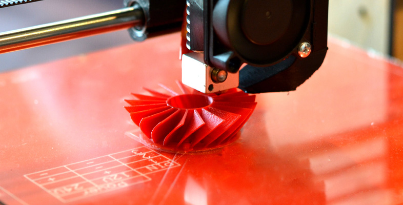
- the build (object being built) stays stationary and the delivery method of material moves – laser beam, print head, and so on
- the material delivery method stays stationary and the build moves.
In both cases the machine uses computer-numerical-control (CNC) for positioning and is fed with the layer data in the STL file.
