Kirchhoff ’s laws
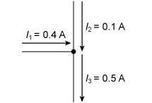
Kirchhoff ’s first law (the current law)
At any junction, or node, in an electrical circuit, the sum of the currents flowing into the node is equal to the sum of the currents flowing out of the node.
This is the same as saying that charge can neither be stored at, nor dispensed from, these nodes. This is a useful rule of thumb – it helps when thinking about problems to be able to distinguish between places where energy can and cannot be stored.
This law is illustrated in Figure 9, where the sum of the currents in the inputs to the node equals the current out.
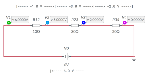
Kirchhoff ’s second law (the loop or mesh law)
When direction is taken into account, the sum of the potential differences around any closed circuit or network is zero. This is illustrated in Figure 10, which is a screenshot taken from an online circuit simulation package called Multisim Live. Here, starting with the battery, the voltages around the circuit are 6.0 V − 1.0 V − 3.0 V − 2.0 V = 0 V.