
3.2 The Wheatstone bridge
Originally developed in the nineteenth century, a Wheatstone bridge provided an accurate way of measuring resistances without being able to measure current or voltage values, but only being able to detect the presence or absence of a current. A simple galvanometer, as illustrated in Figure 13, could show the absence of a current through the Wheatstone bridge in either direction. The long needle visible in the centre of the galvanometer would deflect to one side or the other if any current was detected, but show no deflection in the absence of a current.
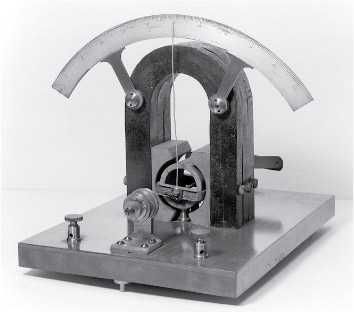
Figure 14(a) shows a circuit made of four resistors forming a Wheatstone bridge. Its purpose here is to show whether there is any current flowing between and . Figure 14(b) shows an equivalent way of drawing the circuit.
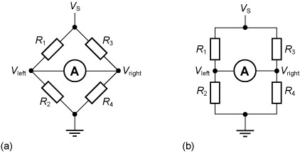
The bridge is said to be balanced (that is, no current flows through the bridge and the needle of the galvanometer shows no deflection) if the voltages and are equal. It can be shown that the bridge is balanced if, and only if, , as follows.
When then . Then the Wheatstone bridge can be viewed as two voltage dividers, and on the left and and on the right. Applying the voltage divider equation gives and .
So
and
Multiplying out the brackets gives
which simplifies to
and
So, if were unknown, , and could be chosen so that the needle of a galvanometer showed no deflection due to the current. Then
SAQ 4
Assume the Wheatstone bridge shown in Figure 14 is balanced. If , and , what is the resistance of ?
Answer
By the formula given in the text,