Skip to content
Skip to main content

About this free course

Download this course

Share this free course

An introduction to electronics

Start this free course now. Just create an account and sign in. Enrol and complete the course for a free statement of participation or digital badge if available.

3.4  Designing a sensor circuit

Figure 17 is a screenshot taken from Multisim Live, showing a circuit with four parts. On the right is a light-emitting diode (LED) and a 470 Ω resistor, cap r times italic five. On the left there is a device called a light-dependent resistor (LDR). This is labelled cap r times italic two and forms a voltage divider with a fixed resistor cap r times italic one. The resistance of the LDR has been measured as 380 Ω in full ambient light and 1.5 kΩ in the dark. We want the LED to switch on when the environment begins to darken and the resistance of cap r times italic two is 680 Ω or more. (Note that cap u times italic one is the label that Multisim Live gives to the op-amp.)
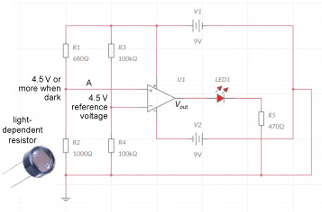
Described image
Figure 17  Circuit diagram for an open-loop op-amp switching an LED (screenshot from Multisim Live)

The resistors cap r times italic three and cap r times italic four form another voltage divider, which will provide a ‘reference’ signal. Both cap r times italic three and cap r times italic four have resistance 100 kΩ. Battery cap v times italic one provides 9 V, so the reference voltage is

nine postfix times cap v prefix multiplication of cap r times italic four divided by left parenthesis cap r times italic three plus cap r times italic four right parenthesis equals nine postfix times cap v prefix multiplication of 100 postfix times 000 postfix times cap omega divided by left parenthesis 100 postfix times 000 plus 100 postfix times 000 right parenthesis postfix times cap omega equals 4.5 postfix times cap v

If cap r times italic one is set to 680 Ω and variable resistor cap r times italic two is also 680 Ω, the voltage at A will be the same as the reference voltage, because

nine postfix times cap v prefix multiplication of cap r times italic two divided by left parenthesis cap r times italic one plus cap r times italic two right parenthesis equals nine postfix times cap v prefix multiplication of 680 postfix times cap omega divided by left parenthesis 680 plus 680 right parenthesis postfix times cap omega equals 4.5 postfix times cap v

As it gets darker, this voltage will increase.

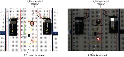
This circuit is shown implemented as a breadboard in Figure 18. When it gets dark and the sensor receives less light, the LED illuminates as required.

Described image
Figure 18  Breadboard circuit for the open-loop op-amp: (a) in light conditions, the LED is not illuminated; (b) when it gets dark, the LED is illuminated