

4.9 Amplifying signals
Most of the electrical signals that record sounds are very weak. For example, a guitar pickup generates electricity as the metal string vibrates in a magnetic field. The amount of electricity that can be generated in this way is limited and typical voltages are in the order of 100 mV. To become useful, this signal needs to be amplified. This means, literally, that the amplitude of the signal has to be increased.
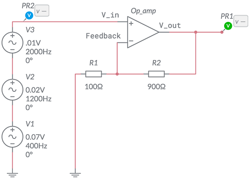
One way to amplify a signal is to use an operational amplifier (op-amp) with two resistors connected to form an amplifying feedback circuit, as shown in Figure 37.
The gain of the amplifier is defined to be
where is the input voltage and is the output voltage. For this kind of circuit, the gain is given by the formula
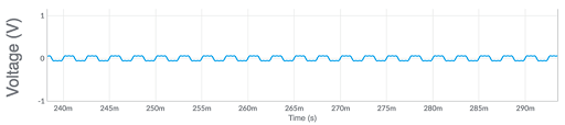
The circuit in Figure 37 is made using the Multisim Live simulation package. The three circular objects on the left are here used to generate a signal. V1 generates a voltage sine wave with amplitude 0.07 V and frequency 400 Hz. V2 generates a voltage sine wave with amplitude 0.02 V and frequency 1200 Hz. V3 generates a voltage sine wave with amplitude 0.01 V and frequency 2000 Hz. Together, they generate the very weak signal shown in Figure 38.
SAQ 18
- a.What is the gain for the circuit shown in Figure 37?
- b.What would the resistor have to be to make the gain 100?
Answer
- a.
b.Rearranging the equation for in terms of gives
So for a gain of 100, with = 100 Ω,
The original circuit shown in Figure 37 gives the result shown in Figure 39.
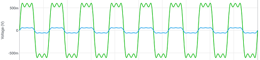
Op-amps are able to amplify signals many thousands of times. Here the amplification is by a gain factor of 10 so that the signal and the amplified signal can both be seen on the same scale. Typically a signal of 100 mV would be amplified by a factor of 50 or more to bring the result to the order of magnitude ±5 V. Some signals from sensors are much weaker and may require a gain in the order of hundreds or even thousands.
This concludes your lightning visit to the world of electronic signals and filtering. You have seen how effectively noise can be removed from a signal, and how different sounds (such as ‘yes’ and ‘no’) appear in both the time and the frequency domain. As well as investigating the theoretical properties of signals, you have seen how they can be amplified using op-amps. If you are interested in going further, a version of the Multisim Live simulator can be used online at no cost – see www.multisim.com [Tip: hold Ctrl and click a link to open it in a new tab. (Hide tip)] .