
2.3 Minerals and the polarising microscope
2.3.1 Introduction to the polarising microscope
The polarising microscope enables the examination of mineral grains and observation of the properties outlined in Section 2.2. A polarising microscope is very similar to an ordinary microscope except that it has two polarising filters and a rotating stage on which the sample is placed. Figure 34 illustrates a typical layout. Plane-polarised light is produced by passing white light through a polarising filter (the polariser) located beneath the rotating stage.
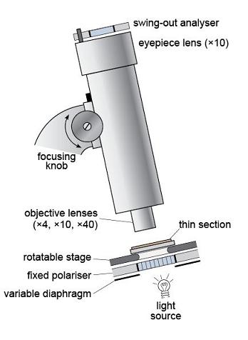
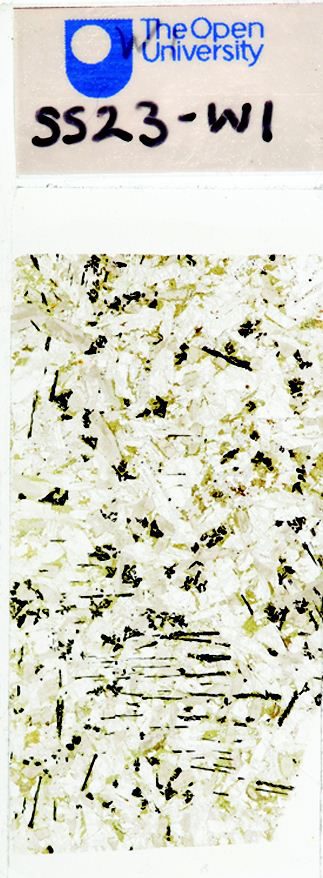
The plane-polarised light then passes through the sample, which is presented as a thin slice of rock, 30 µm thick, mounted on a glass slide - this is a thin section (Figure 35). A magnified image is produced using two sets of lenses: a lower, objective lens, and an upper, eyepiece lens. The magnification can be varied by changing the objective lens. The image is focused by moving the lens assembly up or down, using the focusing knob. It is usual to start by looking at a thin section using plane-polarised light and low magnification. After this, the second polarising filter, the analyser, can be inserted to view the specimen between crossed polars.
In this course, the Virtual Microscope substitutes for the polarising microscope. You will have the opportunity to familiarise yourself with the features and functionality of the Virtual Microscope in Activity 2.1.
The process of creating virtual microscope slides for Earth science creates image files of roughly 1GB for each thin section specimen using a motorised XY stage on a Leica DM4000M microscope. Rotation movies are digitised using an in-house system motorised Leica DM RP microscope.
Activity 2.1 Introduction to the Virtual Microscope
Task 1
This activity introduces you to the interface and functionality of the Virtual Microscope.
During this course, you will be using the Virtual Microscope, a system for viewing and exploring microscope slides (thin sections) of rocks using a computer and an internet browser window. The Virtual Microscope reproduces, and in some cases extends, the capabilities of the real microscope.
Open the Virtual Microscope [Tip: hold Ctrl and click a link to open it in a new tab. (Hide tip)] and you should see a screen similar to the one shown in Figures 36 and 37. We will use the gabbro thin section to illustrate the Virtual Microscope, but this may not be the image that appears the first time you access the Virtual Microscope.
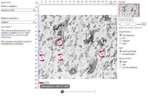
The screen is divided into a main viewing window and several functional areas that provide the ability to pan around the thin section, change magnification and light transmission conditions, and allow measurement (Figure 36).
In the upper left-hand corner, the catalogue of specimens can be accessed via two drop-down menus. The upper menu allows you to choose a sample category from the collection of geological thin sections, including different rock types, characteristic examples of particular minerals and various diagnostic features. The lower menu is a list of links to all the samples within your chosen category. You can use the collection to reinforce your learning and for reference during your Virtual Microscope studies.
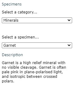
Clicking and scrolling down the upper menu allows you to select from the menu of grouped igneous, metamorphic and sedimentary rocks, a cleavage slice of gypsum, rocks associated with a mapping activity later in the course, or a series of 'unknown' thin sections. There are also many other specimens that are not used in this course. Select 'Gabbro' in the 'Igneous' category for this demonstration.

Gabbro
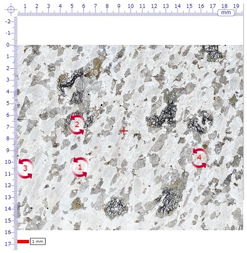
The main window shows the full thin section view when initially selected from the menu. In the middle of the field of view there is a small cross (traditionally called the 'cross hairs' because real hairs were used in early microscopes); this is used for locating features in the specimen (see point 5).
Note that a small number of red, numbered, circular arrows are visible. These are 'hot spot icons' that, when clicked, open a new window displaying rotatable images for viewing in plane-polarised light (left-hand circle), and between crossed polars (right-hand circle) (Figure 37).
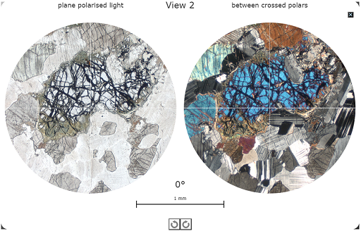 Figure 37 A view of one of the rotatable views (View 2) for the Gabbro page in the Virtual Microscope.
Click the small black box with a white cross in the top right-hand corner of this screen to return to the main viewing window
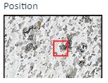
The image in the main window can be manipulated either by zooming in and out, or by panning around the specimen at selected magnifications. As the main image is zoomed or panned, the thumbnail image in the top right-hand corner shows the location of the main window as a red rectangle superimposed on the thumbnail image. The dimensions of the field of view of the main window are given in millimetres on the right above the image ‘Magnification’ heading.
The image can be moved in several different ways by:
- clicking and dragging the image itself
- using the four arrows on the right below the thumbnail image (further explained in point 6)
- clicking and dragging the red rectangle on the thumbnail image in the top right-hand corner
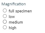
The image magnification can be changed in various ways:
- If you wish to zoom in on the current position of the cross-hairs, simply double-click anywhere within the field of view. Another double-click zooms in further.
- Zooming in and out can also be achieved using a mouse scroll wheel (if available), or the computer keyboard. Press the 'A' key to zoom in, and the 'Z' key to zoom out.
- A slider below the main viewing window can be used to zoom in and out; see point 6.
- Finally, there is a set of fixed magnifications, similar to a series of fixed objective lenses in a real polarising microscope, that can be used to standardise magnifications for some activities; see point 8.
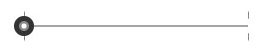
A scale bar below the main view window on the left shows 1 millimetre.
From the main viewing window for gabbro, click on the red arrowed circle labelled ‘2’. The window that appears will display two circular images known as 'rotating views'. At this point, two high-resolution animations are loaded into the browser. The circles may be blank while this is happening.
- the view on the left is an area of the thin section displayed in plane-polarised light
- the view on the right is the same area of the thin section displayed as it appears between crossed polars.
The high-resolution animations may take several seconds to load, but take considerably longer over a slow internet link.
These rotating views are used to demonstrate several of the key optical properties of minerals in the thin sections: in plane-polarised light (PPL) and between crossed polars (XP). They can also be used to measure angles using the simple numerical indicator that lies centrally above the 1 mm scale bar.
The images in these views (i.e. PPL or XP) can be rotated to view changing colours (pleochroism or interference colours) and extinction by clicking and dragging either image using the mouse, or by clicking one of the circular arrows located below the 1 mm scale bar at the bottom of the screen.
Click the small black box with a white cross in the top right-hand corner of this screen to return to the main viewing window.
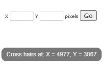
The location of the cross hairs is constantly displayed below the viewing window as X and Y coordinates. The sample can be moved to a specific location by typing the X and Y coordinates into the boxes and clicking the 'Go' button or by pressing the return key on the keyboard. This useful feature allows locations of particular features to be specified and communicated between different users.
Below and to the right-hand side of the main viewing window are a series of image manipulation controls. Use the slider at the bottom of the window to zoom in (right) and out:
Click on the arrows to the right of the window to move the viewing window across the thin section in the direction indicated.

We recommend that you try all the ways of moving the thin section and changing its magnification, to see which are best for you.
At the top right-hand side of the main window, a thumbnail image of the main window displays a red rectangle showing the location of the current field of view within the thin section as a whole.
Fixed magnifications are required for some tasks, and can also be used to switch quickly between magnifications and compare grain sizes at the same magnification in different thin sections.
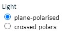
Each thin section can be viewed in plane-polarised light and between crossed polars. Switch between the two views using the labelled buttons.
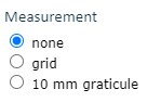
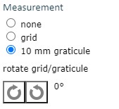
To the lower right of the thin section view are two tick boxes labelled 'grid' and '10 mm graticule'.
When the '10 mm graticule' box is selected, a 10 mm graticule with 0.1 mm divisions is superimposed over the thin section view, allowing direct measurement of features anywhere in the thin section once the features are moved to the centre of the field of view.
Two curved arrows rotate the graticule and grid to measure features in any orientation.
When the 'grid' box is selected, a grid that does not change in size with magnification is superimposed on the thin section view. The grid can be used to define an area for study at a particular magnification, and is especially useful to estimate proportions of different minerals in a view
The colour of the cross hairs and scale bar can be changed by clicking on the 'overlay colour' tick box.

To the left of the thin section view, a description of the rock and its locality are given for each thin section. Minerals and features that appear in blue are hyperlinks to examples in the thin section, many of which are shown in the rotating views.
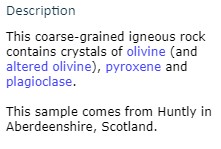
Click 'olivine' in the gabbro description and the thin section view changes to display olivine at an appropriate magnification.
Questions 2.1.1 and 2.1.2 use the Virtual Microscope to view a virtual gypsum cleavage slice ('Miscellaneous' category). You may wish to reflect on the similarities between the two ways of seeing the same phenomenon and additional things you can observe using the Virtual Microscope.
Question 2.1.1
Select the 'Gypsum cleavage slice' from the ‘Miscellaneous’ category of the Virtual Microscope. The single rhomb-shaped crystal fills most of the field of view even at low magnification. By default, the first view will be in plain polarised light. Now select the view between crossed polars. Ignoring the crystal for the moment, why is the field of view outside the boundaries of the crystal clear or transparent in plain polarised light but black when viewed between crossed polars?
Answer
This view corresponds to observation of the gypsum slice between the two sheets of polarised material. (Remember that you learned about minerals and polarised light in Section 2.2.) In plain polarised light, the glass slide on which the gypsum slice is mounted is transparent; however, when viewed between two pieces of polarised material with their polarising directions at right angles, the background and the glass slide appear black. This is because the light is polarised in one direction by the first sheet of polarising material and that direction is blocked by the second, thus allowing no light to pass.
Question 2.1.2
Now consider the crystal slice in the view between crossed polars for the single crystal of gypsum. Given that this is part of a single crystal of gypsum, can you explain the reason for the range of interference colours you observe?
Answer
This cleavage fragment exhibits a wide range of interference colours (including low-order colours at the grain margins on the left-hand side) that correspond with the colours in the Michelle Levy chart of interference colours in Section 2.2.5. This is because it is not a true thin section with a uniform 30 μm thickness, but a broken fragment of a crystal with variable thickness presenting different path lengths to light passing through different parts of it. At its thinnest points close to the edge, the crystal exhibits first-order interference colours, whereas the thicker areas in the centre of the crystal exhibit third and fourth order colours.
Question 2.1.3
Returning to the plane-polarised view, in the main window, click the red-arrowed circle (numbered 1) to open the rotating views in a new window. Explain what you observe as you rotate this part of the gypsum slice in (a) plane-polarised light and (b) between crossed polars.
Answer
- a.On rotation in plane-polarised light, the appearance of the gypsum crystal slice remains the same except for changing from slightly darker to lighter due to varying relief, rather than pleochroism; the darkness of the glass mount beyond the crystal slice also changes very slightly too.
- b.On rotation between crossed polars, the interference colours remain the same, although the brightness varies: every 90°, the crystal slice becomes completely dark. Thus, the crystal slice goes dark four times per complete rotation. The glass slide visible beyond the edge of the crystal slice remains dark in all orientations, as glass is isotropic. When the gypsum cleavage slice is in extinction, you may observe dust on the section and at least one small fragment of gypsum in a different orientation that still shows low-order interference colours when the main crystal is in extinction. In fact, you may also notice that this fragment never goes into extinction because two crystals on top of each other are very unlikely to be completely aligned with the polarisers. One of the reasons that geologists use very thin slices of rock is to avoid this effect and to observe the optical properties of individual crystals in thin section.