
2.3.2 Minerals in thin section
Microscopic examination of a rock in thin section enables its constituent minerals and its textural properties to be identified. These are important and essential steps in establishing a rock's identity and in deducing how it was formed. The Virtual Microscope is designed to provide images as would be seen using a real polarising microscope. Views of numerous rock thin sections are available in plane-polarised light (PPL) and between crossed polars (XP), at different magnifications and at selected rotation points. The main optical properties used to identify minerals in both plane-polarised light and between crossed polars are outlined below. You can view examples of all these properties in the ‘Mineralogical features’ category of the Virtual Microscope.
In plane-polarised light
Relief. Relief is the term used to describe the degree to which edges and surface imperfections of crystals are visible in plane-polarised light. Minerals with a refractive index very different from that of the mounting glue are said to have high relief as they appear to 'stand out' from the slide (as for pyroxene in Figure 38a): grain boundaries are easily seen and surface imperfections appear pronounced. Minerals with refractive indices similar to that of the mounting glue are said to have low relief: individual grain boundaries are not easily observed and the minerals are featureless and almost invisible in plane-polarised light (as for plagioclase in Figure 38b). If the mineral is highly anisotropic (e.g. calcite), the relief may vary as the stage is rotated: the transmitted light sampling first one permitted vibration direction, then the other.
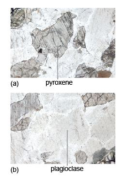
Cleavage. Cleavage traces may be seen as sets of parallel straight lines cutting through a mineral section (Figure 38a). The presence, number and angular relationships of cleavage traces can be diagnostic for some minerals. Micas have one good strong cleavage (Figure 10c); pyroxenes and amphiboles have two cleavage planes, which intersect at about 90º and 120º, respectively, when basal sections are viewed in cross-section (Figure 42).
Colour and pleochroism. Many coloured silicate minerals are rich in iron (e.g. ferromagnesian minerals). If the colour changes as the mineral is rotated in plane-polarised light, the mineral is said to be pleochroic (i.e. the mineral absorbs light differently in different orientations - a concept met in Section 2.2.3). Biotite (dark mica) and amphiboles are good examples of pleochroic minerals, biotite commonly having characteristic pale- to dark-brown pleochroism (Figure 30).
Opaque minerals. Many opaque minerals are metal oxides, such as hematite (Fe2O3) and ilmenite (FeTiO3), or sulfides, such as pyrite (FeS2). Opaque minerals transmit no light - even in 30 µm thin sections: they appear black when viewed in both plane-polarised light and between crossed polars (in any orientation). Opaque minerals should not be confused with non-opaque minerals that are isotropic and appear black only between crossed polars.
Between crossed polars
Isotropic minerals. Isotropic minerals (e.g. garnet and fluorite) belong to the cubic system and, like glass, which is a disordered solid (Section 2.2), always appear black between crossed polars (e.g. the garnet in Figure 44c), regardless of their orientation but, unlike opaque minerals, will transmit light when viewed in plane-polarised light.
Anisotropic minerals. An anisotropic mineral (most minerals) will normally display an interference colour when viewed between crossed polars and will pass in and out of extinction (at 90° intervals) as the stage is rotated. The interference colour depends on the crystallographic orientation of the mineral. When an anisotropic mineral is viewed in an orientation whereby the refractive indices in the permitted directions are the same (i.e. down the long axes of tetragonal, hexagonal and trigonal minerals), the mineral appears dark as the stage is rotated (i.e. it behaves like an isotropic mineral). This would be a basal section.
Interference colour. The Michel-Levy chart is used to estimate whether a mineral has high-order or low-order interference colours. When several grains of the same mineral are present, it is necessary to look for the one that shows the highest-order interference colour, which corresponds to the maximum birefringence.
Extinction. Cleavage traces can also be observed between crossed polars. Because cleavage planes are usually related to crystallographic axes, there is often a relationship between cleavage direction and the position at which the mineral goes into extinction. When cleavage traces are parallel or perpendicular to a mineral's permitted vibration directions, the extinction position is parallel to the cleavage and is referred to as straight extinction. When the extinction position is at an angle to the cleavage trace, the mineral shows inclined extinction.
Twinning. A twinned crystal consists of regions that are structurally related to each other across a twin plane (Section 1.5). These regions are called twin components and, when viewed between crossed polars, adjacent components will go into extinction in different positions. Simple twins comprise just two components, side by side. However, some minerals (e.g. plagioclase feldspar), feature multiple twin components and, when viewed between crossed polars, have a striped appearance (Figure 19c). Rotating the crystal causes the bright and dark stripes to swap over.
Activity 2.2 Exploring mineral properties in thin section
Task 1
For this activity you will require the Virtual Microscope [Tip: hold Ctrl and click a link to open it in a new tab. (Hide tip)] . Use the drop-down menus of categories and sample names to navigate to the thin sections specified.
Question 2.2.1
Look at the thin section of quartzite in plane-polarised light (which can be found under the ‘Metamorphic rocks’ category). It contains many different grains of the same mineral (quartz). Can you see any boundaries between grains? Why are they not very clear? Now select crossed polars. Can you distinguish between different grains more easily? If so, what is the explanation for this?
Answer
Grain boundaries are quite difficult to see in this thin section because it contains just one kind of mineral, quartz, which has very low relief. The grain boundaries are much more evident between crossed polars: different quartz crystals are in different orientations, hence have different birefringence and show different interference colours.
Question 2.2.2
Examine the thin section of peridotite (which can be found under the ‘Igneous rocks’ category), first in plane-polarised light, then between crossed polars. It contains abundant grains of the mineral olivine. How do (a) relief and (b) interference colours of olivine compare with those seen in the quartzite?
Answer
Compared with the quartz crystals in the quartzite, the olivine crystals in the peridotite show (a) higher relief in plane-polarised light and (b) higher-order interference colours between crossed polars.
Question 2.2.3
Look at the granite thin section (which can be found under the ‘Igneous rocks’ category) in plane-polarised light. Note the brown mineral. Select one of the rotating view hot spots containing the mineral. What happens to the colour of this mineral when it is rotated in plane-polarised light? What is this phenomenon called? What is its origin?
Answer
In plane-polarised light, the colour of the brown mineral (biotite) changes as the slide is rotated. This phenomenon is called pleochroism; it is caused by a variation in the absorption of light, depending on the orientation of the crystal relative to the polarisation direction.
Question 2.2.4
Look at the thin section of schist (which can be found under the ‘Metamorphic rocks’ category). Note the large, equidimensional (garnet) crystals in plane-polarised light. These crystals seem to stand out from the slide and have more surface texture than the surrounding minerals. They are said to have high relief. How does the relief of these crystals compare with the relief of the other crystals in the slide? Now look at the thin section between crossed polars. What happens to the garnet crystals when the stage is rotated? What term describes crystals that exhibit this property? From this optical behaviour, what is the crystal system of garnet?
Answer
The garnet crystals have much higher relief than the other crystals. Viewed between crossed polars, the garnet crystals are black, and remain so as the stage is rotated, whilst the other crystals display a variety of interference colours ranging from low-order to high-order colours. The garnet crystals are therefore optically isotropic, and so must belong to the cubic system.
The next section will focus on the recognition of the main rock-forming minerals using these properties. You can find many more rocks presented on the Virtual Microscope collections website, created by The Open University in partnership with several other organisations with funding from JISC.
Although optical microscopy still has great value, providing an essential contextual framework for studying minerals and deducing how their characteristics and interrelationships reveal the manner of their formation, there are today many sophisticated procedures that can be used to extend our knowledge of minerals. A flavour of some of these is provided in Box 3.
Box 3 Determining mineral chemistry
Nowadays, interpreting the behaviour of rocks during their formation and subsequent events requires the chemical composition of their constituent minerals to be quantified. This can be done with modern instrumentation. In particular it can be important to determine the composition of individual grains, and even the variation within a grain. Appropriate modern microanalytical techniques use the electron microprobe (EMP), laser ablation inductively coupled plasma mass spectrometry (LA-ICP-MS) and the ion microprobe (IMP).
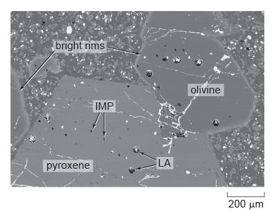
The electron microprobe technique involves directing a focused electron beam at a polished surface of a mineral grain. X-rays that are specific for each constituent element are emitted from the mineral. By measuring the intensity of the X-rays that characterise different elements, the major and minor element composition of 'spots' only a few μm across can be obtained. Alternatively, the beam may be scanned across the surface of mineral grains to produce X-ray maps of elemental concentrations. Another way of mapping minerals is by back-scattered electron (BSE) imaging. This is an image of the electrons that are scattered or bounced back by atoms bombarded by the electron beam. The number of electrons back-scattered is proportional to the mean atomic mass of the spot under the beam. So, brighter areas of the image represent minerals containing heavier elements (e.g. Fe and Ca) and darker areas represent minerals containing lighter elements (e.g. Si, Al, Mg and Na) (see Figure 39).
LA-ICP-MS uses a laser probe to melt a hole in a mineral; the vaporised (ablated) material is then analysed by mass spectrometer for its trace element, and sometimes its isotope, compositions. Spot sizes are 40-100 μm; which is generally larger than those of the EMP, but lower concentrations can be determined.
The ion microprobe uses an ion beam to remove (sputter) very small amounts of material from a spot 100 nm to 40 μm in size. The sputtered material is then analysed by mass spectrometer for its isotope and trace element compositions.
These micro-analytical techniques can be used to investigate the crystallisation history of an igneous rock. The back-scattered electron image in Figure 39 shows several large crystals of the minerals olivine and pyroxene surrounded by finer-grained crystals in a lava from the Solomon Islands in the western Pacific. EMP analysis reveals (Figure 40) that the bright rim around the edge of the olivine crystals is rich in iron, but the iron content decreases inwards until, from about 50 μm in from the rim, through the central part of the grain, the olivine has a constant (magnesium-rich) composition. This chemical profile is interpreted as being due to the diffusion of iron and magnesium between the surrounding magma and the olivine crystal just prior to eruption of the lava. The large pyroxene crystal also has a regular compositional variation around its edges, but this can be revealed only by LA-ICP-MS and IMP analysis of the trace element contents, which increase near the edge of the crystal.
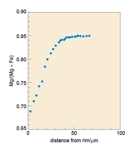
If the temperature of the lava is known (by calculation from the chemistry of the lava and the minerals), it is possible to use the diffusion profile (the compositional gradient) in the rim to calculate how long the crystals had resided in the melt just prior to eruption. In this example, diffusion modelling reveals that the large crystals were there for 13.8 ± 1.4 days at a temperature of 1100 °C. This was long enough to produce the iron-rich rim of the olivine. The uniform internal compositions indicate that these crystals had originally crystallised elsewhere in the magmatic system.