
3.5 Systems maps
Definition
A systems map is a snapshot of a system and its environment at a given time.
Note that 'system' has a specialized meaning here. It is the term used to describe any situation or issue you want to explore. It is what you are interested in investigating and hence is known as the system of interest. A system of interest is separated from its environment by a boundary. Boundaries also exist between components of a system ( or sub-systems).
A system of interest (SoI) is defined by its purpose. The purpose thus represents the general boundary of a system. The components of a systems map are therefore related to each other as if they collectively fulfil that purpose. Examples of a SoI could include an entity like an organization or an activity like planning an intervention.
A systems map shows how themes or elements might be grouped together as components of the specified SoI or as elements in the environment of the SoI. Some components might be grouped together (or bounded) as sub-systems. Single components might themselves be sub-systems.
A systems map derives from the perspective of the person or people constructing it. A systems map thus illustrates boundary judgements.
Use
Systems maps help to identify the themes and elements that you see as being relevant to an issue. Where you draw the boundaries for your SoI is key to deciding at what level to focus upon. For example, is a particular development project an appropriate focus for intervention? It might be more beneficial to focus down a level, examining one aspect of the project, say the budgetary or personnel component. Or conversely, it might be more beneficial to go up at different levels and to focus instead on the policy domain, programme or strategy in which the project is embedded. Perhaps a global focus might be more appropriate than a regional, national, or local focus. Development practice is continually informed by such boundary judgements.
Once a particular level of interest (e.g. level of intervention) is decided upon, systems mapping can prompt investigation into the following types of boundary judgement or questions.
- What is the purpose of intervention? (What exactly is the SoI?)
- What needs to be done to fulfil that purpose? (What are the components of the SoI?)
- What obstacles might there be to fulfilling that purpose? (What are the elements in the environment?)
In addition, systems maps can be used to analyse existing systems of interest. They can:
- signal and question exactly what is (as against what ought to be) in the SoI (for example, stakeholders involved in an intervention)
- signal and question what is (as against what ought to be) in the environment (for example, relevant stakeholders marginalized from the process of intervention, or other factors outside the terms of reference that might be relevant to the success of the intervention).
In brief systems mapping can be used to:
- Clarify thoughts at an early stage of analysis.
- Establish structural elements for a more detailed diagram.
- Experiment with systems boundaries.
- Focus on a level of interest (and various sub-systems of interest within it).
- Communicate to others the basic structure of the SoI you are describing.
Diagram components
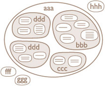
- A title defining the purpose of your SoI (the situation or issue you are exploring).
- Blobs (regular or irregular rounded shapes) to show the boundaries of the system, sub-system components, and elements in the environment.
- Labels within the blobs to describe the system, sub-system components, and elements in the environment.
Note that lines and arrows are not used within systems maps.
Conventions and guidelines
In drawing a systems map the main steps are as follows.
- Identify the main issue on which you are going to draw a system of interest.
- Draw the main boundary around your system of interest, thereby specifying what falls within the system itself and what is in the environment.
- Identify each sub-system and draw a blob around it to establish its boundary.
Use words within appropriate boundaries to name
- i.the system (this will be the title of your main system of interest)
- ii.component sub-systems, and
- iii.elements in the environment.
- Blobs (boundaries) may occasionally overlap if some components are seen as belonging to more than one system. However, you should overlap only when the sharing of components is important from your particular viewpoint or when you are still uncertain as to where a component should lie. Overlaps generally work against the aim of clearly identifying a system of interest.
Don't worry if it takes several iterations through each step before you are happy with your diagram, or even if it takes several versions of the diagram. Each time you draw or redraw the diagram helps to clarify or refocus your thinking about the situation or issue you are investigating.
Activity 8 Animated tutorial 3
Watch the animated tutorial (click on ‘View’ below) to see how I built up my systems map of the WWP. If you are still a bit unsure about what a systems map is you might like to view the optional animation, What is a systems map?, before viewing the WWP example.
Click on systems map [Tip: hold Ctrl and click a link to open it in a new tab. (Hide tip)] to see the description of the animated tutorial.