
1.4 Example 2: The Bridge of Sighs (and Wobbles)
The second example of a systems failure is the Millennium Bridge across the Thames linking the St Paul's area of the City of London on the north side of the river with a new cultural centre emerging in Southwark on the South Bank.
The bridge was to be solely for pedestrians, and was an idea first put forward by David Bell, who was at that time Editor of the influential Financial Times newspaper. The paper sponsored an international design competition which was won by a consortium of the architects Foster and Partners under the leadership of Lord Foster, Sir Anthony Caro, the distinguished sculptor and Ove Arup, the well-known firm of consulting engineers. All three members of the consortium had international reputations for innovation and the quality of their artistic and design capability. Foster and Caro's concept for the bridge was daring and imaginative. Foster, inspired by the light beam of legendary superhero Flash Gordon, envisioned a ‘beautiful blade of light’.
The bridge was one of a number of similar projects that had been stimulated by the success of Santiago Calatrava's Alamillo Bridge built for Expo'92 in Seville and the Erasmus Bridge, opened in 1996 in Rotterdam and designed by the architects UN Studio. These projects demonstrated that bridges could be potent symbols of a particular time and location and could engage the local community. Caroline Bos, co-founder of UN Studio, recalled, ‘Designing the Erasmus was an incredible experience for us because the local community was so excited about it.’ (Financial Times, 3 June 2000)
These bridges made use of new technology and materials to support innovative designs that were intended to support growing cultural tourism. The footbridge across the River Tyne at Gateshead uses a new pivoting mechanism that allows it to swing open to enable ships to pass underneath. Roger Ridsdill-Smith, an Ove Arup associate, commenting that the design of the Millennium Bridge could not have been attempted ten years previously, stated, ‘An engineer then would have understood the physics of how the bridge stands up but wouldn't have had the confidence to do it. High powered computers have given us that confidence by allowing us to test our calculations. The structure is so fine that, when people stand on the bridge, they'll feel as if they're hovering over the water.’ The importance of the bridge to tourism was emphasised by Lord Foster: ‘When a foreign visitor comes to London, they will remember buildings like St Paul's or Tate Modern, but also the experience of moving around. Crossing the Millennium Bridge – devoid of cars, buses and trucks – will be one of their most vivid memories.’ (Financial Times, 3 June 2000)
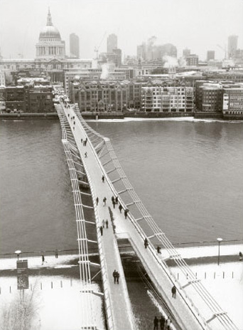
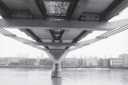
The ‘beautiful blade of light’ was to be the first bridge constructed across the Thames for over a hundred years, since the building of Tower Bridge in 1894. The design was not without some criticism, most notably from the Swiss architects of the Tate Modern conversion, Herzog & de Meuron (Financial Times, 10 May 2000). An impression of the design of the bridge can be gained from the photographs in Figure 5 and Figure 6.
Work was launched on the sleek steel structure by the Deputy Prime Minister, John Prescott, at a ceremony held on 28 April 1999. The construction work was to be undertaken by a joint venture team of Sir Robert McAlpine and the Danish specialist bridge-builders Monberg Thorsen (The Times, 28 April 1999). The opening was predicted to be April 2000 and the estimated cost was £15 million. This was a considerable increase on the original estimate of £9 million. Most of the funding for the project came from the Millennium Commission, the Corporation of London (through the Bridge House Estates Trust) and the Hong Kong and Shanghai Banking Corporation (HSBC).
The 330-metre structure was designed for pedestrian use only. The shallow suspension structure is supported on two piers, with a central span of 144 metres. The weight of the bridge is carried by four 120-millimetre-diameter cables on either side attached to the deck by arms and anchored with abutments on the banks. The cables and the deck of the bridge dip by 2.3 metres over the central span. The design had to comply with several requirements. First it had to allow the navigation of a variety of ships up and down the river. At present the largest of these is the 2000-tonne Tracey Bennet, a commercial sand and aggregate carrier, which is 55 metres long. The design team undertook extensive studies of the effects that the impact of such a vessel would have on the bridge. The second consideration was that of stiffness.
The Institution of Civil Engineers’ Dynamics Design and Practice Guide (Maguire and Wyatt, 2002) points out that ‘dynamics is a far more important subject to civil and structural engineers than it used to be, because structures have become lighter, members (structural elements) more slender. These changes have increased amplitude of vibration and moved frequencies into bands that are more awkward to deal with and more easily perceived by users.’ This consideration is particularly important for footbridges since ‘most walkers on a sensitive bridge instinctively adjust their pace to the response in a way that maximises excitation.’ (Maguire and Wyatt, 2002). This well-known phenomenon is the reason that marching soldiers are ordered to break step when crossing a bridge.
With these points in mind,
The original design assumptions regarding dynamic loading by pedestrians were checked. The guidance in the relevant UK bridge design codes had been followed, with additional input from overseas codes and non-statutory documents. The codes advise on the level of force to be assumed in design, and the amount of movement which is acceptable to users of a bridge.
The UK bridge codes require only vertical excitation to be considered. In the original design all critical vertical modes of vibration were examined. The size of the applied loading recommended in the bridge design code was increased by 33 per cent to give the design additional robustness. The original design also considered loading due to groups of vandals deliberately attempting to excite the bridge.
Extensive additional research was carried out during the original design, including database searches on suspension bridges.
(Arup, 2000a)
However, perhaps the consideration that was at the forefront of the bridge designers’ minds was the need for the structure to be both innovative and aesthetically bold. In this Lord Foster and Sir Anthony Caro did not have it all their own way. Sir Anthony blamed planners for interfering with the design and said that they had ‘cut down and trampled on’ innovative ideas (Yahoo, 2000).
The bridge did not open in April 2000 as originally planned; engineering problems and a strike at the Finnish company supplying some of the steel members delayed completion. The final cost of £18.2 million (Financial Times, 11 July 2000) had risen by £3 million in the year of construction and had doubled the original estimate of £9 million. The Queen performed an opening ceremony on 10 May 2000 but was unable to walk across the bridge as it was still in an unfinished state.
To celebrate the opening of the bridge to the public on Saturday 10 June, 100,000 people crossed it in a charity walk in aid of the Save the Children fund. Problems were immediately apparent and police closed the bridge as it began to sway alarmingly in only a light wind. A similar problem had occurred earlier in the year when a pedestrian bridge in Paris, linking the Quay d'Orsay with the Tuileries gardens, was closed after the French Minister for Culture, Christine Trautmann, was upset by similar movements (Financial Times, 12 June 2000).
The Millennium Bridge remained open the following day but only 150 people were allowed to cross at one time. Even so, some visitors complained that they could not walk in a straight line, and of feeling seasick. Others enjoyed the experience. Kay Clapton from Kent stated, ‘If they repair the bridge it won't be the same. The thrill of walking across the Thames as the bridge is swaying is amazing.’ (Financial Times, 12 June 2000). In spite of reactions such as this from the more adventurous, the decision was taken to close the bridge. Ove Arup explained:
The bridge was open for three days, between Saturday 10 June and Monday 12 June. At times it was very crowded, with some 2000 people along its length. An estimated 80,000–100,000 people crossed on the opening Saturday. When the bridge was crowded, the south and centre spans suffered lateral vibrations large enough to cause pedestrians to stop walking or to hold onto the balustrades to regain their balance. The movement of the south span, between Bankside and the first river pier, was a combination of horizontal and torsional (twisting) oscillations. Observations on the day and studies of video footage show up to 50 mm movement, depending on the number of people walking. The frequency of the movement was about 0.77 cycles/second.
The centre span moved by up to 70 mm at a frequency of 0.95 cycles/second, mainly horizontally. This part of the bridge was observed to oscillate when occupied by more than about 200 people. The north span did not move substantially.
It was decided to control the number of people present on the bridge from noon on the Saturday onwards. The concern was the safety of individuals, rather than any risk of structural failure of the bridge itself.
The bridge was closed on 12 June pending investigation into the cause of the unexpected movements.
(Arup, 2000a)
There followed weeks of intensive investigation. The Building Research Establishment provided specialist shaking equipment that was used to replicate the forces acting on the bridge. A group of 100 Ove Arup employees crossed the bridge in an attempt to replicate the behaviour of groups of people in response to instability. Vertical and horizontal loading were monitored at key points by the Transport Research Laboratory during the tests, which were filmed from four locations.
As a result of these tests the engineers went back to the model that they had used to check the original design. The work had been undertaken following best practice principles, which require the design and analysis to be carried out independently by two separate teams. The results of the work of these teams was then checked. In addition, the work was validated by an independent firm, who conducted their own analysis. All this work was replicated using data from the tests.
The results of this review and comparison show that, apart from the unexpected movement, the bridge is reacting as predicted. There are some marginal – and explicable – differences in the figures but none represents a significant departure from the model, and none could explain the unexpected movement.
(Arup, 2000b)
The problem of the wobbling bridges seemed to be caused by people walking across it! At one level of analysis this assessment was correct. However, the potential problem caused to the structure of bridges by soldiers marching in step was well known. The problems experienced by the Millennium Bridge had a different origin, to do with induced walking in step and the bridge structure. As groups walk across the bridge the natural cadence of their steps may coincide with the horizontal frequencies of the bridge structure. If the movement brought about by such a coincidence becomes noticeable to those crossing they will tend to adjust their walking pattern in order to feel more stable and, inadvertently, respond in a way that ‘maximises excitation’, as the Institution of Civil Engineers’ Dynamics Design and Practice Guide (Maguire and Wyatt, 2002) points out. According to an expert, Professor Jonathon Wood, who had worked on a similar problem on the Severn Bridge, ‘The Millennium Bridge has almost no lateral stiffness and virtually no torsional stiffness.’ The Times, 31 October 2000)
Midway through September 2000 Ove Arup was in a position to report on its investigations. It confirmed that the wobble had been caused not by the lack of lateral and torsional stiffness in the original design but by ‘large groups of pedestrians [who] had appeared to be stepping in time with the motion of the bridge.’ On its website, Arup notes:
A programme of research was undertaken during the summer of 2000. A solution was then developed using the results of these tests. Arup has warned other bridge designers of their findings and the British Standard code of bridge loading is being updated to cover the phenomenon, now becoming referred to as Synchronous Lateral Excitation.
The research indicated that the movement was caused by the sideways loads we generate when walking. Chance correlation of our footsteps when we walk in a crowd generated slight sideways movements of the bridge. It then became more comfortable for people to walk in synchronisation with the bridge movement.
This instinctive behavior ensures that the sideways forces we exert match the resonant frequency of the bridge, and are timed such as to increase the motion of the bridge. As the magnitude of the motion increases, the total sideways force increases and we becomes more correlated.
The sway movement is not specific to the Millennium Bridge. The same excessive sway movement could occur on other bridges, future or existing, with a lateral frequency under ~1.3 Hz and with a sufficient number of pedestrians.
During the investigations Arup discovered that other bridges with completely different structures to the Millennium Bridge have swayed sideways when crowded, for example the Auckland Harbour Road Bridge during a demonstration in 1975 […]. These cases have not been widely published and as a result the phenomenon has not become known to practicing bridge engineers.
(Arup, 2005)
The engineers considered four solutions. Two of these were rejected early in the analysis. These were solutions to limit the number of people using the bridge at any one time, or to modify walking patterns by introducing obstructions. These options were considered to be undesirable and a last resort to be adopted if no other solution could be found.
The engineering team estimated that stiffening the structure to alter the ‘natural frequency range of the bridge sway modes away from the frequency range of lateral forces from pedestrians’ would require a nine-fold increase in lateral stiffness in the centre span of the bridge. As a result, heavy bracing would be needed. This solution was rejected because it would have required, in addition, conventional dampers to be fitted. The total weight of such a scheme would have meant further modifications to the bridge's structure and foundations. It would also have altered the appearance of the bridge.
The solution adopted, subject to a satisfactory trial, was to fit two sorts of damper to absorb the vibrations created in the structure. Viscous dampers, which operate like car shock absorbers, restrict the flow of a viscous liquid contained within the device. These were to be fitted between the existing structure and some additional steel bracing. Tuned mass dampers were also to be used to provide additional control of both vertical and horizontal movements. Preserving the appearance of the bridge was of special importance to the members of the consortium. Ove Arup (Arup, 2000a) stated:
Protection of the elegance of the bridge has been a key aim. The design solution has evolved in weekly meetings with Foster and Partners and discussed in detail with Sir Anthony Caro and Lord Foster. […] The additional structure and dampers under the bridge deck do not affect the side elevation since they are located above the level of the transverse arms and therefore behind the deck edge tubes. The structure which will be visible on the bridge elevation will be:
The diagonal viscous dampers at the piers. These are located in the plane between the cables and the edge tubes and extend two bays along on each side of the pier.
The two viscous dampers on each side of the south abutment ramp. These are arranged as an inverted ‘V’ and are located on each corner of the ramp junction where it splits in two and turns parallel to the river bank.
The underside of the bridge is an important feature of the design. One of the main views of the bridge is from each bank and from river boats, where the soffit is plainly visible. The chevron shaped bracings have been designed with this in mind and are aligned with the bridge centreline and spaced at regular intervals. Similarly, the tuned mass dampers are arranged regularly and placed between the underside of the deck and the top of the transverse arms.
The proposed solution was tested using the model, the analysis confirming that the dampers would cure the wobble or at least limit movement to ‘acceptable levels’. Further modelling was undertaken to test the solution in exceptional circumstances. Finally, tests were to be carried out on individual components and a prototype test carried out to determine the dynamic behaviour of the bridge with a set of dampers fitted.
In late November 2001 work finally started on the modifications. Ove Arup paid a reported £250,000 to have two viscous dampers and one tuned mass damper fitted to the central span of the bridge. These paved the way for the full solution, which was estimated to cost £5 million.
SAQ 3
Make brief notes in answer to the following questions:
-
What was the problem that occurred at the brief abortive opening of the bridge in June 2000?
-
What work was undertaken to define the problem in detail?
-
What measures of performance were used evaluate the proposed solutions?
-
What solutions were considered?
-
How were the solutions evaluated?
Answer
-
The bridge wobbled to an extent that discomforted some users and might possibly have been hazardous.
-
Extensive tests were carried out in an effort to understand the problem and to identify its cause. A shaking machine was brought in and groups of Ove Arup employees walked across the bridge in an attempt to replicate the problem. The movement of the bridge was monitored and filmed using video cameras. The results of the tests were fed into the model that had been used to validate the original design.
Advice was taken from experts in the field and the behaviour of other bridges was researched.
-
First, the proposed solution had to solve the wobble problem to reduce the movement of the bridge to an acceptable level. Second, it had to avoid degrading the appearance of the structure.
-
Four solutions were considered:
-
restricting the number of people crossing the bridge at any one time;
-
breaking up the stride pattern of people crossing;
-
stiffening the bridge;
-
damping the bridge's movement.
-
-
Two of the possible solutions were considered to be impractical. The stiffening solution was rejected on engineering and aesthetic grounds. The damping solution was tested using the model. Individual components were tested. Finally a prototype was installed on the bridge and was tested.
Multiple-cause and sign-graph diagramming are techniques that can be used to identify and understand the relationships between the various elements in a situation.
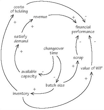
Recently I was discussing with a group of colleagues the importance of reducing the time that it takes to change over from one job to another on a factory floor. In a ‘semi-brainstorming’ mode we quickly drew the diagram shown in Figure 7 on a flipchart.
The arrows connecting one element in the diagram with another should be read as meaning ‘influences’, ‘affects’ or ‘contributes to’ rather than ‘causes’. For example, the changeover time affects the available capacity of machines in the costs of holding system. We added ‘+’ and ‘−’ signs to indicate the ‘direction’ of the influence of one element on another. The ‘−’ sign indicates that, for example, as changeover time increases, the capacity available for production decreases. The changes in the two elements work in opposite ‘directions’ to one another, so it would also be true that an increase in changeover time would be accompanied by a decrease in the capacity available for production. The ‘+’ is used to designate an influence where movements in two elements work in the same direction, so that if inventory increases, the value of work in progress (WIP) will also rise. Similarly, if inventory falls, the value of WIP will fall.
I said earlier that Figure 7 was the result of a semi-brainstorming session. As such it was an initial statement that needed considerable refinement. It was certainly not the ‘finished product’ but played a valuable part in getting the team started.
SAQ 4
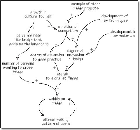
Draw a multiple-cause diagram that would provide an initial understanding of the reasons for the wobble problem on the Millennium Bridge.
The problems of designing software that works have been apparent for forty years and those associated with designing and building bridges for thousands of years. This collective experience has not stopped designers and engineers making mistakes, which are often expensive in terms of time and resources. Autodesk spent millions of dollars developing Workcenter but abandoned the product soon after its launch. The original budget for the Millennium Bridge was £9 million; the final cost, including modifications, was approximately £23 million, approaching three times the first estimate. The opening of the bridge was planned to coincide with the launch of the Tate Modern in April 2000 but failed to meet that date.
In both cases the designers and engineers were being innovative. They were trying to operate towards the right-hand end of the spectrum of change illustrated in Figure 3. This makes the endeavour risky and, therefore, mistakes more likely. This does not mean that we should avoid risk. Life would be a lot duller if risk avoidance were always the norm. In the two examples, and with the benefit of hindsight, it is clear that both sets of designers failed to conceive their projects appropriately. The software engineers at Autodesk thought that they were building a software package rather than a product that would have to include both software and consultancy. Lord Foster and Sir Anthony Caro wanted to design a beautiful bridge. In doing so they lost sight of its function. In both cases a more holistic methodology might have prevented the problem that occurred. Systems engineering aims to provide such a methodology.