

5.2 Down to the detail
A little later I will describe an example of a product undergoing this process of defining the detail where you can follow the decisions that are made. First I will give some general examples to give a feel for the range of design activities used in transforming concept into prototype.
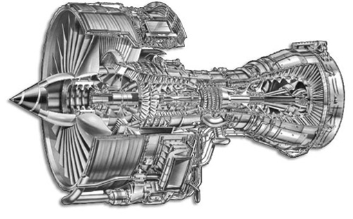
First think of a jet engine used in a commercial aeroplane. There are three major designers and manufacturers of these in the world: Rolls-Royce, General Electric, and Pratt and Whitney. All three are trying to apply new science and engineering to making engines that are more powerful, more efficient and quieter. Figures 29 and 30 show a jet engine to give you some idea of the scale and complexity of this product.
A design team will have made decisions on materials, configuration of inlets, blades, burners and exhaust, temperature of operation, size, and power output.

Some of these will be determined by specific needs in the industry tied to the operating conditions, types of aircraft, payload and range. At this stage there are many ideas incorporated into a concept. For example, a particular material may be chosen but there may still be uncertainties as to how it is to be manufactured in the shapes and surface finishes required. To run the jet at a high combustion temperature may require cooling channels in the blades. Maybe this has been done successfully before but perhaps not at the temperature needed for a new jet. The loads on bearings for all flight conditions may not be known accurately, but based on experience and preliminary calculations the design team will have defined a range of sizes and shapes.
There still is considerable design work to complete in defining (i) shapes and surfaces, (ii) geometry and configuration of cooling channels so that they can be produced without weakening the blades and (iii) specifying bearings (probably for detail design and manufacture by a third party supplier). There are many possibilities for each of these which need exploring. Models which use mathematics, computers and practical testing are used to determine the performance of different possible details for the designs.
Think of a new car. A concept design for a new model will cover areas such as shape and initial styling (see Figures 4 and 6), and engine configuration, suspension and transmission. The types of these may be suggested, but not in any detail. There is still major design effort needed to transform a body style into a pressed and welded bodyshell; to specify the gears, bearings and shafts in the gearbox for the operational loads; to specify engine components for performance, efficiency and cost.
Exercise 7
Suggest three reasons why defining the details of a design can take a long time and considerable effort.
Answer
My suggestions are:
There are likely to be many choices for the details.
Constructing models (probably computer models) of the design and studying the behaviour of the models is likely to be time consuming.
Testing and evaluating possible designs to find a best or a satisfactory solution is laborious. Note that finding a best design is very difficult and time consuming in complex problems. The costs in time and money of small improvements in performance can be large when we are close to a good solution.
It is at this stage between concept and prototype that models of designs are widely used. Designers need to predict the performance of possible designs without building a complete prototype at large cost: a prototype of a vacuum cleaner may be economically feasible, but a prototype of a jet engine is less so. The predictions will not always be entirely accurate because as we have seen, models are always incomplete in some respects. The models do not include all the factors which influence the design when in use. However, they are a help and guide in progressing through this stage of design. The models help designers to make choices among possibilities in the design space.
Sometimes this part of the process of design is seen as rather routine. The excitements of looking at new concepts or the building and of testing of prototypes are real and tangible. However, there is substantial scope for creativity. Just because the concept stage has defined limits on possible designs does not mean that this part of design is boring and mechanical. Making good decisions in developing detail depends on understanding the close relationships among different parts and features of a design. Balance, compromise and judgement are needed. This is equally creative as the grand schemes and broad brush at the concept stage.
So in trying to define the details of a design we might try many possibilities. Some parts of the design may be right and others wrong. As a result of putting right one part, another part may go wrong. Designers try and learn from this exploration of design possibilities and 'home in' on a good design.
In order to look at design possibilities at the concept-to-prototype stage of design, you might like to look at a game, The detail design game. This is not real design of product (we will examine a real product later) but it is an illustration of some of the ways of thinking that designers use.
The detail design game
Suppose a design is to be made which consists of three modules, and within each module there are several components. Each component is a simple rectangular unit. Within modules, the components are connected end-to-side as shown in Figure 31.
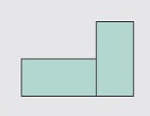
Connections between components within modules can only be end-to-side. There should be no accidental edge-to-edge connections between components in any other way. For example, the connections between components shown in Figure 32 are not allowed inside a module. We must make sure that these 'invalid' connections do not accidentally arise whilst making valid connections.
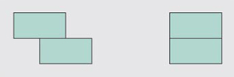
Connections between modules, however, are made by connecting components inside the modules side-to-side, as in Figure 33. There must be no accidental connections between modules in any other way.
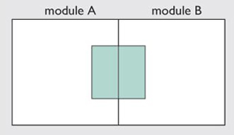
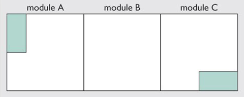
Suppose that a conceptual design has determined that three modules are needed to be connected in a row. There must be one component in the top left corner and one in the bottom right (this might be for connecting this group of modules to another group). Figure 34 shows this arrangement.
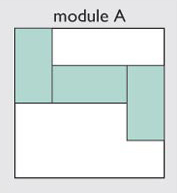
We might start in module A as shown in Figure 35. This has three components inside the module. Note that each module does not need to be entirely filled with components. (You might ask at this stage whether there are any other ways to connect components in Module A.)
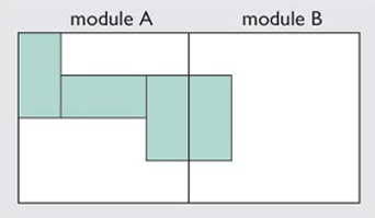
To connect Module B you need to add the first component in Module B along the long edge of the third component in Module A, as in Figure 36.
The design problem is to connect components in each module and connect modules according to the allowable connections. There are potentially many solutions.
SAQ 12
Try to find one solution to the game by sketching layouts of components on Figure 34. The aim is not to find the best solution but to reflect on how you obtained a solution.
Reflect on how you arrived at your solution. How did you go about solving the problem?
Answer
There are many solutions!
Perhaps you might have used the following:
Look at failures and avoid similar layouts of connection.
Look ahead in your 'mind's eye' to connections in the next module.
Make a modification to a failure.