
3.9 Failure of replacement gears
A heavy commercial vehicle company announced that it would no longer supply spare parts for one of its vehicles. This was a problem for customers, as the two largest gears in the gearbox tended to wear faster than the others and it became impossible to replace them even when the other parts still had a great deal of useful life. A specialist firm set out to manufacture spare parts and soon had orders for dozens of sets of these two particular gears.
This firm had measured the gears and manufactured new ones of identical dimensions, using one of the strongest steels available. It machined the gears and sent them out for heat treatment as, in addition to hardening and tempering the whole gear, the teeth had to be surface hardened to match the hardness of the originals.
All seemed to be well until a pair of gears was returned, having failed by teeth breaking off in just over three weeks' service. The failure was assumed to be due to poor driving. So another pair was put in the gearbox, but a similar failure occurred in less than one week.
The problem was then easily identified by comparing the new gears to the originals.
The gears were made of steel that started off as cast billets. In the as-cast state, the steel has no directionality to its microstructure but, as it is worked down to billet or bar, directionality appears as grains and inclusions are extended in the direction of working. The directionality is revealed as 'flow lines' which resemble the grain in timber. For any given quality of steel, the strength is much better across the flow lines than in parallel with them).
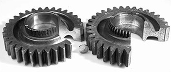
Figure 38 is a view of the gear showing the inner upper ring of teeth which were breaking off. A radial section was cut from the original gear and a similar one from an unused new gear. These were polished and the flow lines revealed by etching. Figure 39 shows the old gear at the left and the new gear at the right. The teeth which were breaking off were the small ones which are at the top in the sections of Figure 38. In the old gear they are worn down, which is why the gears needed replacing. The unused new gear shows the teeth in side profile. The section has been cut so as to include the full section of the large teeth around the outside.
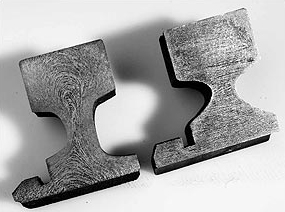
What difference is there in the flow lines in these two sections?
In the new gear they all run parallel to the axis and, if this were made of wood you would expect them to break off easily. In the old gear the flow lines are in a looped, radial pattern tending to run at right angles to the gear's axis. If you look carefully at the small teeth you will see that they run pretty well at right angles to the direction of the flow lines in the new gear.
The original gears had been forged before the teeth were cut, whereas the replacements had been machined directly from round bar. The flow lines tell us that the old gears had started off as a length of round bar about twice as long as the gear is thick, but of smaller diameter. This was hot forged to squash it down, causing the outside to spread out so that the shape finished up with a much larger diameter and shorter length than when it started. This was done specifically to develop the flow line pattern you can observe. When the teeth were cut, the grain flow was oriented at right angles to the applied bending stresses in service. The teeth were thus as tough as they could be for this type of steel and the flow lines were oriented in directions which imparted the maximum resistance to failure.
In contrast, the new gears had been machined from stock of the full diameter the gear required. There was no forging, so the flow lines remained parallel to the gear axis.
The result was that the flow lines in the teeth were in the most unfavourable orientation to resist fatigue and brittle fracture. This is why they broke off so quickly under service loads, despite having the same hardness (and tensile strength) as the original gears.
SAQ 8
-
Which of the processes covered so far could be used for making the cap and body for a ballpoint pen? Start by classifying their shapes.
-
On cheap versions of such pens, there are often thin lines running the length of the body and/or the cap. What do you think is the origin of these lines?
Answer
-
Both of these are non-continuous 3D hollow items, so injection moulding would be used.
-
The lines are 'flash' from the join between the two mould surfaces; more expensive pens will have had the lines polished off after moulding.