
5 A problem in bicycle design
5.1 The development of the bicycle
Section 4 has looked at how we can follow a logical route or map, from the expression of a need, to arrive at possible solutions to a problem. In Sections 5 and 6 we look in more detail at two quite different examples of engineering problems. Our first example is the historical development of the bicycle frame; the second concerns a vital component of a car's airbag system.
The weight of a bicycle frame is a major burden that the cyclist has to bear. There have certainly been times when I felt I needed a lighter bike, usually when going up hills. So, I want us to begin 'identifying and evaluating solutions' for the problem of how to make a bicycle frame lighter, while retaining its performance. A little historical background is important as we are not the first to address this problem.
The modern bicycle frame is central to a huge international business, dominated by American and Chinese markets. In the USA, current estimates put the market at about 15 million bicycles per annum and, in an increasingly environmentally conscious society, the future looks pretty much guaranteed. In this context, the bike is a mature product in an established market, but at some point in history there were no bicycles and the first design must have been produced in order to meet a need. We can guess that this need was for a mode of transport that was quicker than walking and that didn't need feeding.
In fact, the first vehicle that worked with two wheels in a line (the very basic characteristic that came to define a bicycle) was introduced in France in 1791 with a non-steering front wheel, no pedals and a wooden horse's head! For its time, this 'bicycle' was an innovation, and unbelievably it didn't change much for the next twenty years or so. In 1817 a steerable front wheel was introduced (in Germany) and pedals made their first appearance in 1839 (in Scotland). The chain, the sprocket-driven rear wheel and equal-sized front and back wheels were added in England in the early 1880s and were followed by pneumatic tyres, two- and three-speed hub gears and then derailleur gears before the turn of the century.
Each of these major changes came about through engineers finding solutions through innovation by context, but along the way there were literally hundreds of small innovations by development and numerous routine design improvements. For example, in 1879 Charles E. Pratt wrote in his handbook The American Bicycler:
From 1868 until the present time the patented improvements have been numerous, and the mechanical details of construction have been thoroughly worked out, until the machine has become a marvel of ingenuity and of workmanship; and the modern bicycle has been developed to its present state of perfection in strength, lightness, ease of propulsion, certainty of control, and gracefulness of design and operation.
This is an accolade that would swell any engineer's head, but it implies that any advances since 1879 have been extraneous!
SAQ 8
The pneumatic tyre was a novel use of a sealed tube of pressurised air to provide the running surface of a bicycle wheel. Say whether you view its introduction as an innovation or a routine improvement.
Answer
The pneumatic tyre was an innovation by context. Tyres had not been made in this way before, though the idea of sealing pressurised air into a container was not new (e.g. balloons, footballs, etc.).
An interesting aside to the technological advancement of the bike is in respect of the effect that engineering has on society. The bicycle is generally attributed as being pivotal in the liberation of women in the USA and Europe. Women in England were able to travel independently and in relative safety for the first time, particularly after Queen Victoria made it a socially acceptable practice by riding her tricycle alone in public. A postmistress in the USA, Amelia Bloomer, designed the first trousers for women – bloomers – specifically for riding bikes. The same Amelia Bloomer went on to spearhead the Suffragette fight for women's right to vote in the USA.
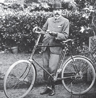
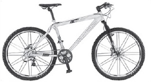
Bringing the bike up to date, the maturity of the contemporary model can be seen by comparing Sir Edward Elgar's Sunbeam of 1903 (Figure 21), a relatively sophisticated design in the history of the bike, with a modern all-terrain bicycle (Figure 22). The ancillary equipment has changed but the functional form of the frame structure is still based on a triangulated tubular diamond shape.
Today's market for bicycles is highly competitive, and manufacturers strive to appear better by being different. The 'engineering problem' that I identified at the start was to do with making a lighter frame. It is important therefore to separate real structural and performance improvements to the frame from fashionable gimmicks that might even add weight. To facilitate such comparisons it is necessary to understand the fundamentals of the product, and that calls for a bit of modelling.
So, back to basics: what is a bicycle frame?
SAQ 9
Write a brief specification (five or six lines) for a bicycle frame, considering its physical form and what it must be physically capable of achieving.
Answer
In engineering terms the need is for a space frame that enables two wheels to be held in place and supports the forces developed by the rider's mass and his or her efforts. The frame should be rigid enough to keep the rear wheel in line with the chain wheel, which is attached to the pedals. In addition the front forks must also rotate to allow the front wheel to steer at low speeds.
The bicycle can be seen as a variation on a seven-membered truss (Figure 23), a frame structure that is a common element in structural and mechanical engineering.
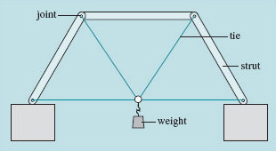
If the axles of the wheels replace the side supports, the bike begins to reveal itself, as shown in Figure 24.
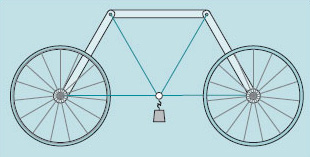
This structure is capable of supporting a central load as shown and will clearly subject the truss-based space frame to the same in-plane forces – compression in the struts and tension in the tie-wires. There are only a few simple adjustments left to turn the basic structure of Figure 24 into a 'functional' bicycle frame configuration, Figure 25.
One of the tie-wires has been removed in order to allow the front wheel to rotate, and the strut attached to the front wheel has to be free to rotate at the pin joint. Add a saddle, chain, pedals and handlebars and away you go.
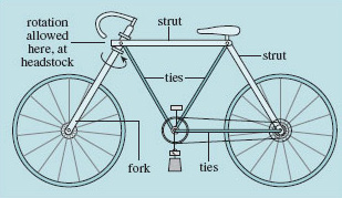
By making a comparison with a simple structure that can be fully analysed, we have been able to confirm the fundamental elements of the bicycle structure, the bit that carries the major forces. However, there is a difficulty. As we shall see in the next block, Figure 24 represents what is called a statically determinate structure. Removing one component risks turning it into a mechanism: that is, it may change shape in response to forces. Removing the bottom-left tie in the truss of Figure 24 would cause it to collapse unless something were done to rectify or compensate for its absence. If part of the top-left pin joint is fixed and does not allow the attached side-strut to swivel about the joint axis, the strut is turned into a cantilever, which restores stability to the structure but at a price. The original strut, now acting as a cantilever, is no longer subject to just axial compression, but has additional forces that lead to bending about the frame region called the headstock. Such a configuration creates high stresses in the material, in this case reaching a maximum at the top of the cantilever fork close to the headstock. The relatively simple problem of allowing this cantilever to rotate is soon solved by the use of bearings that can support forces whilst rotating. Hence, the 'bicycle' shown schematically in Figure 25 could function, if manufactured from adequate materials for the struts, ties and cantilever.
The next thing to do is to see how we can, in general, evaluate solutions based on different materials. Then we'll reintroduce the specific needs of a bicycle frame.