
5.3 Back to the bicycle
Let's assume that our bicycle frame could still be constructed from ties and struts. If we want to select the material to minimise the weight of a frame for a particular frame strength, we need to devise a merit index as follows.
The mass of the tie-rods and struts needed for the frame is given by:
Therefore,

where h is the length of a component and A is its cross-sectional area. The failure force for tensile yielding, F, is given by:

in which σy is a property of any chosen material. Eliminating A from Equations (1.1) and (1.2) gives:
Usually we want a materials-based index that gets bigger the better the material. Hence it is better to express our index in terms of (1/m), which gets bigger the lighter the frame.
Hence, rearranging Equation (1.3) gives:
Now for a tie-rod of particular length h, able to resist a particular force F, the bigger the value of the material merit index (σy/ρ) the lighter the frame could be for the same performance.
From identical considerations, the bigger the value of (σc/ρ) the lighter a frame could be made for a specified performance.
Using a comparable approach you can also select a merit index to find light struts and ties that limit elastic strain, giving a particular deflection under a given load.
In these circumstances selecting the material with the highest value of (E/r), where E is the Young's modulus, has the potential to give the lightest frame components that deflect by a particular amount under load.
Table 4 shows absolute values and some merit indices for a range of recently used frame materials.
| Characteristic: | σy | σc | E | ρ | |||
|---|---|---|---|---|---|---|---|
| Units: | MN m−2 | MN m−2 | GN m−2 | kg m−3 | kN m kg−1 | kN m kg−1 | MN m kg−1 |
| Material: | |||||||
| Alloy Cr—Mo steel | 700 | 700 | 210 | 7870 | 88 | 88 | 26 |
| Aluminium alloy | 350 | 350 | 70 | 2800 | 125 | 125 | 25 |
| Titanium alloy | 650 | 650 | 105 | 4500 | 144 | 144 | 23 |
| Carbon-fibre composite | 500 | 200 | 60 | 1100 | 454 | 181 | 54 |
| Magnesium-based alloy | 300 | 300 | 45 | 1780 | 176 | 176 | 25 |
You can see the great potential for carbon-fibre composites and the strong competition between the other frame materials, particularly for the deflection-based index E/ρ. However, there are three major limitations that need consideration before we all go out and start manufacturing carbon-fibre bike frames for a living:
Firstly, because the frame is subjected to much more complex load patterns than axial tension and compression within ties and struts, it turns out that additional merit indices are required.
Secondly, the figures for carbon-fibre composite are based on idealised production conditions where the optimum amount of carbon fibres can be reliably incorporated into the appropriate matrix, whereas the figures for the metallic alloys are those that can be expected regardless of manufacturing conditions.
Finally, the techniques needed to manufacture advanced composites in complex three-dimensional shapes with good surface finish are extremely expensive, so the external factor of cost limits the potential market to the successes and failures covered in Box 10 Carbon-fibre composites to win at all costs .
Box 10 Carbon-fibre composites to win at all costs
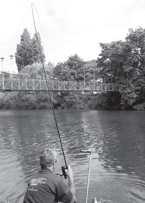
The development of commercially viable carbon fibres for engineering purposes was only made possible because large quantities, supplied to the sports goods industry, sustained early progress and allowed prices to fall to acceptable levels. The fishing rod and golf club shaft industries have to be thanked for supporting the manufacture of very expensive early production quantities. The high ratios of tensile strength to weight allowed golf club shafts to deflect to higher values without snapping. For some players this increased the distance of their tee shots. The same properties were also very attractive for whippy fishing rods that had higher strengths than equivalent bamboo and glass-fibre predecessors, Figure 27.
SAQ 10
Identify the types of need for which carbon-fibre tubes are attractive solutions.
Answer
The need is for lighter tubular structures that have the same, or better, strength and stiffness characteristics as compared with conventional materials.
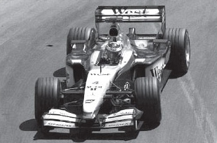
More recently, carbon-fibre composites have been used to make other simple structures that benefit from the high E/ρ ratio for the material. Lightweight products that give minimal deflections include wing sections for aerospace vehicles and racing cars (Figure 28), and 'roach poles' for fishing, which make it possible to use a particular technique to reach further across wide stretches of water than was previously manageable.
Very recently there have been some great successes and failures associated with complex three-dimensional carbon-fibre composite products. In cycling, a carbon-fibre composite frame which is very light and very stiff has been found not to be indestructible – at least one has failed in an accident under conditions that a metal frame might have survived.
Exercise 4
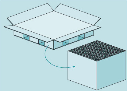
Many short stubby struts, or 'chocks', used for supporting dry-docked ships, stored goods, vehicles and the like, need to be made as cheaply as possible. Figure 29 shows an example of a cardboard pallet. Table 5 gives values of crushing strength ρc and cost C in euros per cubic metre for some materials.
(a) Derive a merit index that increases as the total cost K of supporting compressive load L with a strut of height h decreases. Hint: You will need to introduce the cross-section area A into the total cost and the maximum load – you can then eliminate it from a combination of the two expressions.
(b) Calculate the index for the candidate materials in Table 5, and select the cheapest option.
| Material | Crushing strength σc/MN m−2 | Cost C/€ m−3 |
|---|---|---|
| Softwood | 7 | 40 |
| Hardwood | 15 | 20 |
| Mild steel | 300 | 1500 |
| Recycled thermoplastic | 18 | 560 |
| Cellular cardboard | 0.7 | 15 |
Answer
The cross-section A needed is given by:

The total cost K is given by:

The number 1/K will increase as the cost K goes down.
Rearranging the equation and substituting for A gives:
Hence for a fixed load L and strut height h the required merit index is σc/C. Hence, not surprisingly, materials with a high crushing strength to low cost per unit volume are preferred. You should note that this analysis does not place a limit upon the space required by the cross-section of the strut A, which can get large for low-density materials. I have calculated the merit index for each of the materials, Table 8.
| Material | σc/C/ MN m €−1 |
|---|---|
| Softwood | 0.17 |
| Hardwood | 0.75 |
| Mild steel | 0.20 |
| Recycled thermoplastic | 0.03 |
| Cellular cardboard | 0.05 |
So at these prices the preferred chocks are hardwood, followed by mild steel, hence their prevalence in commerce for such tasks. Note that, although the crushing strengths are unlikely to change, the relative prices can change in response to local availability, which can influence the merit index.
Returning to the analysis of the bicycle frame, although the frame shown in Figure 25 could function, its performance would be limited to resisting forces in the vertical plane of the frame. Unfortunately, it is essential that frames resist the out-of-plane forces that are generated when a cyclist leans the bike over for hill climbing, sprints and cornering as shown in Figure 30.
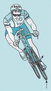
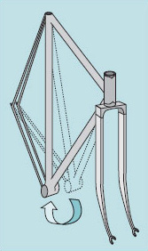
This is when the maximum stresses are generated, as other forces add to the rider's own body weight. Flexible tie-wires and even thin rods have no resistance to such bending forces and so must be replaced by solid cantilever devices that have bending and torsional resistance, to limit the deflection shown in Figure 31. The pin joints are also eliminated to add to this bending resistance.
Finally, as can be seen in Figure 31, the rear triangle is divided to allow the rear wheel to be centrally located, and the front forks are usually divided in a similar way to produce the familiar bicycle-frame configuration. Such deflections are an indication of the overall frame stiffness.
In this section, although we have revealed the potential for using different materials, we have not found a 'best solution' for a lighter frame. In fact, we have done what often happens in the search for solutions. We have refined the problem and demonstrated our need to know more technical background, especially on the behaviour of loaded structures.