
4.11 Model for pier failure
Figure 39 shows a simple model to explain the failure of the piers. The lateral wind loading on the top of the pier bends to shear the pier from a rectangle into a parallelogram. In turn, this stretches the tie bars and also strains the bolted joints at the top and bottom of each column.
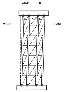
You will notice the tension induced in the bars by the stress is shown in the tie bars as you might expect if they were all equally loaded by the tilting. The tension load will, however, be in addition to that already present from tightening of the joint when the bridge was built.
The second point is that the greater part of the load will be experienced by those tie bars directly in line with the direction of stress, the wind bracing tie bars aligned on an east-west axis. They are the set of tie bars in the centre of the pier.
The induced tension in the outermost tie bars (corner faces) will be somewhat less because they are aligned at an angle of about 45° to the east-west axis of each pier.
The inner set of tie bars aligned along the axis of the railway line should experience little or no stress because they are at right angles to the side-to-side movement of the bridge.
There should also be little or no tension in the horizontal struts if the entire structure distorts. Unlike the tie bars, they cannot be pre-tensioned because they have no gib and cotter joint. Indeed, they are designed to act in compression rather than tension. Any overall lateral distortion of the pier will lead to twisting at their attachment points however. They are attached to the top double lugs by two bolts, which should give extra security against twisting provided the joint is tight and there is little play between the bolts and the holes in which they sit.
The horizontal tie rods that cross diagonally within the pier are also unaffected by tilting of the pier. That is, they should not be tensioned by overall distortion of the pier shown in Figure 39. As the wind loading is increased, eventually the bracing tie bars and bolted joints will fail and the pier will collapse to the eastern side of the bridge.
Question 6
Examine the visual evidence shown in Figures 23–36 (see Sections 3.3, 4.4, 4.5, 4.6, 4.7 and 4.8) and identify features you think support the simple tilting model. Can you think of any alternative failure mechanisms that are consistent with the evidence?
Be cautious in your interpretation of the remains, because once a pier has started to give way, subsequent stages in the collapse may be highly unpredictable.
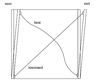
One way to explore further the simple theory is to examine a single cell of the structure, as shown by the diagram in Figure 40. The cell is defined by the two columns on either side and the two horizontal struts, with the pre-tensioned diagonal tie bars running from corner to corner of the cell.

Answer
As is usual in such cases, the problem is essentially one of distinguishing between damage caused by the collapse, and damage that led to the collapse. Support for the theory of collapse to the east comes from inspection of several key pictures from the BoT collection.
The first set of pictures from the totally collapsed piers 4 and 5 (Figures 23, 24, 25 and 26) show the west-facing columns fell almost as a group to the east. The two east-facing lugs (left- and right-of-centre in Figure 24) are broken through the bolt holes, and the columns themselves have broken behind the lugs to leave sharp projections. Those broken lugs could support the theory, but further corroboration is vital. The similar set of base lugs on pier 4 lie beneath the fallen columns (Figure 26), and so may have been further damaged during the final stages of the collapse.
Figure 27 shows the two broken diagonals facing the east, which would have broken from their lugs when pier 3 leaned over to the east. The upper tiers of pier 3 sheared away at the flanged joints to leave the lowest tier only. Figures 28, 29 and 30 show the broken lugs on the east-facing diagonal tie bars, a failure mode that appears to be a widespread problem in the structure.
Similarly, Figure 31 shows nine lug ends that have fallen to the floor of pier 3. They cannot all have come from the lowest tier and it is tempting to suggest they came from east-facing tie bars higher up the pier as the entire pier became unstable. As they lie to the east part of the platform, they may have been thrown here by elastic recoil from the column bases higher up the pier.
Figure 32 shows more complex damage on pier 1, but there are clear parallels with pier 3. All east-facing lugs on the centre part of the two tiers have broken, so leaving the tie bars swinging free, although some of the west-facing tie bars on the outer parts of each set of triangulated columns have broken.
This suggests at some stage during the collapse, the pier may have swung to the west before the top set of tiers fell to the east. The idea seems to gain some support from the presence of a large spall at the base of the right-hand column in Figure 32, perhaps caused by the structure swaying to the west, because the spall faces east. Figure 33 shows the broken lugs on the platform, further supporting the idea that the single base lugs were of low strength.
The standing pier 28 (Figures 34, 35 and 36) shows collateral damage probably caused in the final stages of the collapse when the high girders were pulled off the pier. Some of the damage on the centre part of the pier may, however, have been caused at an earlier stage in collapse. It is difficult to see, for example, how some of the east-west tie bars could have been damaged by fall of debris from the top of the pier because the struts above are intact (for example, the lowest east-facing broken tie bar on the bottom tier – a little out of alignment, is bottom of Figure 35).
So there is support for the theory from the visible remains, although collapse of the piers was more complex than the simple theory suggests. An alternative hypothesis is that tilting occurred in both directions before the final critical event. In other words, tilting may have occurred to the west as well as to the east, that is, the bridge oscillated.
Question 7
The simple tilting model has ignored the trailing diagonal tie bars, which are compressed as the pier becomes a parallelogram. Is this reasonable? To help visualise the situation, sketch the tie bars using Figure 40 as the model. Identify any supporting evidence in Figures 23–36 (see Sections 3.3, 4.4, 4.5, 4.6, 4.7 and 4.8) and specify any backlash possible in the cottered joint (Figure 18).
What will be the effect of tilting to the west on the diagonal tie bars?
Answer
The diagonal tie bars have a section of 2.25 square inches (Figure 18). In axial compression, the diagonal bars will easily buckle (see Figures 41 and 42, below) and will not be able to support an appreciable compression load. The assumption is therefore reasonable.

In addition, there will be some slack to be taken up in the bolt holes at each end and also in the cottered joint. With reference to Figure 18, note that the cottered joint can move by approximately 0.5 inch in compression before it can lake any compressive load – so there is 0.5 inch of backlash in the joint. Supporting photograph evidence is available in the form of badly bent and buckled diagonal bars (Figures 24, 25 and 26).
Tilting the pier to the west (Figure 42) will have the opposite effect. That is, the tie bar with its lower lug facing west will be tensioned, while the other tie bar will be compressed and hence buckle under the load after taking up the slack in the gib and cotter joint.