4.5 Photographs showing the detail: broken lugs
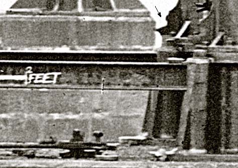
The bases of the columns to which they were attached originally on pier 3 deserve closer inspection. Even at this scale, the two fractured lugs where the tie bars were formerly fixed are clearly visible at the right-hand and left-hand sides of Figure 28 (arrowed). The southern (left-hand) column base in Figure 28 is shown at about ×8 magnification in Figure 29, below, and it is now possible to see the fractures more clearly.
The lug originally comprised two wings standing proud of the column surface, an intact lug being seen in section at the right-hand side of the same picture. It possesses a round outer edge, which blends in a smooth curve with the upper surface of the column, and more abruptly with the bottom flange of the column pipe.
The joint consists of a pair of metal sling plates that enter the slot between the two lugs and fasten by a single bolt that passes through the plates and lugs. The same intact lug also shows the way the two plates were connected to the single long tie bar, with a gib at extreme right, and two cotters jammed into the slot (see also Figure 18). The only problem with this interpretation is there seem to be four parts in the slot: has the joint been modified? The cotters were split pins, deliberately opened to prevent them slipping out of the joint.
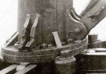
The way the southern lug has fractured seems clear (Figure 29): the lug has broken across the bolt holes. The fracture surfaces appear rougher than the immediate adjacent metal surfaces, and there are slight differences between the crack paths in each lug. The southern lower fracture surface appears substantially rougher than the other parts of the broken components.
The other interesting feature of the break is the profile of the bolt holes: they are conical in section, tapering from narrow outer diameters to wider inner diameters. It was common practice in casting to provide a taper so that the core that formed the hole could be withdrawn easily without damaging the mould sand. They cannot have been drilled, but must have been cast to shape in the mould. The corresponding break at the northern lug (at right in Figure 28) is very similar in form.
The broken southern lug can also be seen in cross-section in Figure 27, at the base of the third column from the right. The section torn away is a sector of slightly more than 90°, and the remains of the hole at its apex is just visible. A high magnification of the column base is shown in Figure 30, below, with the lug arrowed. Another broken tie bar appears to be lying on the stone platform.