
4.7 Photographs showing the detail: damage to pier 1
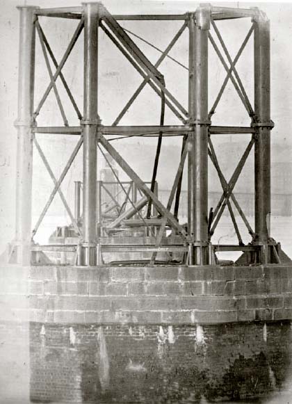
The final example of a partly collapsed pier is pier 1, photographed from the base of pier 28 and shown in Figure 32. Fracture damage to the flange at the top of the second tier is visible on the east-most column (top right); a large chunk of metal has broken off. The southern column (right of centre) exhibits a matching fracture where the parts are still held in position by the wrought iron strut. Propagation of the same crack has also released the top lug, with the tie bar and strut still attached, so they hang in the centre of the pier.
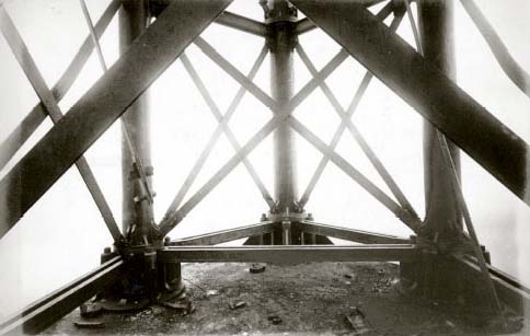
The damage overall is more severe than in the case of pier 3, but it is still possible to identify the pattern of fracture to the principal components. The second picture of pier 1 is shown in Figure 33: a view of the platform looking west towards the western columns. The image has been made lighter and the contrast increased to highlight parts lying on the platform and their fracture surfaces.
Question 5
Summarise and explain the damage to the principal parts of pier 1 visible on Figures 32 and 33, above. Be careful to survey the picture systematically, including any interesting features that might help to clarify how failure of specific components occurred. Distinguish between wrought iron and cast iron as the material of construction for those various parts you include in your survey. Include a comparison of the damage here with that visible on similar parts of pier 3.
Answer
In addition to the damaged cast-iron columns at the top of the tier already mentioned, further damage can be seen at the base of the right-hand column (Figure 32). It is where a large piece of the wall of the column has spalled away to expose the cement filling. Such damage might have been caused by a brittle crack running up from the base flange, itself initiated by bending of the column to the west.
The same movement could account for the damage to the top of the same column, but it cannot explain the damage to the top of the adjacent column (second from right in Figure 32), which was probably caused by bending of the higher columns to the east.
Similar contradictory comments apply to the tie bars, more having failed than in pier 3. Starting with the centre bracing structure, the lower part shows fracture of both of the east-facing tie bars, with the west-facing ones intact – just like pier 3. They have both fractured at the base lugs. The same is true of the tie bars in the tier above, with the added problem of the fall of the front bar with the strut above due to the flange fracture already noted.
Some of the other diagonal tie bars have broken as well, all of which appeared intact on pier 3. Two are seen in Figure 32, one at the upper tier at left, the other in the section of the structure diametrically opposite, at lower right. As in all other cases of tie bar failure seen in both piers 1 and 3, failure has occurred by brittle fracture of the lower single cast-iron lugs.
Turning to Figure 33, one common feature can be identified immediately, it is the end of the hanging tie bar. It is seen left-of-centre in front of the column, and the end is clearly visible. It is a standard gib and cotter joint attached to a pair of sling plates, and the bolt is still in place within the final holes. It can only have failed by fracture of the pair of lower lugs on the tier above. The lowest tie bar has been moved, presumably by the photographer: it is the tie bar at left in Figure 33. It is resting on the platform floor in Figure 32, but propped against the lower strut in Figure 33.
Figure 33 shows great similarity with the analogous shot of pier 3, especially with the two broken lower lugs and the debris field. The fracture surfaces appear very similar in shape, and there are several lug ends on the floor. There are also bolts and what seem to be cotters among the debris. Overall, the damage is similar, arguing for a similar failure mechanism in both piers.