
5.4 Expert evidence: an overview
The second part of the enquiry was devoted to analysis of the disaster. There were three engineers appointed: Mr Henry Law for the enquiry, and Dr William Pole and Mr Allan Stewart acting on behalf of the NBR. In addition, Mr Law collected samples of columnar material and wrought iron straps, bolts and struts for mechanical testing, as well as many broken parts to be shown as exhibits at the enquiry. He asked Mr David Kirkaldy to test the samples using a hydraulically operated tensometer.
The report by Henry Law is reproduced as Paper 1, and Mr Kirkaldy's results are in Paper 2, both linked below.
Click 'View document' below to open Paper 1 (18 pages, 13 MB).
View document [Tip: hold Ctrl and click a link to open it in a new tab. (Hide tip)]
Click 'View document' below to open Paper 2 (7 pages, 4 MB).
Other experts were brought on as needed, such as Sir George Airey the astronomer royal and Professor Stokes for their views on wind pressures, in addition to numerous meteorologists for wind records. Other civil engineers such as Benjamin Baker and John Cochrane were also called to give evidence.
Question 11
Read the Law Report in Paper 1, linked above, and summarise the way he tackled the problem of explaining the failure of the bridge. Include any important design features of the bridge he discusses, as well as any analysis he performed to arrive at his conclusions. Although certain data was exact and measurable – weight of the train and so on – other critical information was absent, or if available, uncertain. What was the information that was absent, and how did Mr Law tackle the problem of interpretation?
Answer
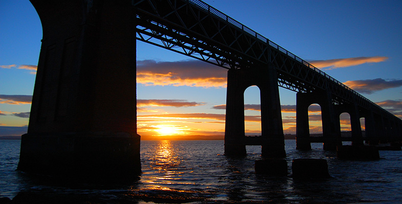
The Law report starts by describing the design of the bridge and how the girders are fixed to the piers. This is important for the way the structure collapsed, because the girders fell effectively as one unit and were little damaged. However, their fixing to the piers was also critical. They were bolted down to the piers only at only three points in the high girders section – shown in the first table presented in the report – and were freely supported at all the other piers. The reason for this was the need to allow for thermal expansion and contraction from temperature changes to which the structure would be exposed in service. In a long bridge, the effect could be substantial, and if not allowed for, could create substantial distortion of the structure.
He then describes in great detail the way the piers themselves were designed, in two sets of three, all being connected and braced to give the essential stability needed of a space frame. Each set of three pier heads was connected together at the top by an L-shaped girder, and surmounted by a plate on which the roller bearings were placed.
There follows a discussion of the four forces the bridge was subjected to and they include:
the dead-weight of the structure;
the live weight of a passing train;
thermal changes;
wind pressure.
The effects of the dead-weight of the structure and the weight of the train were easily calculated in the static analysis he performed. Law ignored the thermal changes in his analysis.
The greatest uncertainty lies in assessing the effects of the wind on the structure. But what area of the structure should be used for the analysis? Law states that he took the assumptions adopted by experts Pole and Stewart regarding surface areas, which involved several simplifying assumptions.
The analysis proceeds by first examining the stability of the train. As the last second class carriage is lightest, it will be most at risk of overturning in a high wind. He found on applying the moment analysis, that a pressure greater than 40 pounds per square foot would have been needed to overturn it. This value compares with an overturning pressure of 28.5 pounds per square foot estimated by Pole and Stewart, the difference being the allowance for passengers in that particular carriage.
He then calculates the wind pressure needed to overturn the pier as a single rigid unit and under two conditions: with and without the train on it. The figures are about 32.7 and 36.4 pounds per square foot respectively.
A better way of tackling the problem of why the bridge fell is by examining the shear strength of the piers. Here the evidence for weakening the structure is strong. Loosening occurred mainly at the gibs and cotters due to vibrations over the life of the bridge, from passing trains and wind action.
Turning to the evidence from the fallen piers, he comments that the key pier 4 over which the train was passing when the structure failed, showed some of the columns had fallen to the west, in the opposite direction to the fall of the girders. Piers 8, 11 and 12 showed a similar effect.
Piers 1 and 3 are also key pieces of evidence because they were the only piers with standing remnant tiers. The way they failed shows ‘conclusively’ there was a weakness exposed at the second tier and first tier respectively. By this, he perhaps means the flanges by which the columns were attached to one another, were weaker than upper or lower flanges, so that they failed preferentially.
This point neatly brings Mr Law to the faults in the way the castings had been made. He starts by observing that the bolts securing the bases of the columns to the masonry were poor. No anchor plate had been used, so any slight changes in the cement filling would allow them to loosen in their sockets. He also observes that the cement bonding adhered poorly to the masonry, and should have been wetted to improve the bond.
Turning his attention to the quality of the cast iron, he saw many defects when inspecting the remains such as variations in wall thickness, blowholes, and so on. Most crucial was the poor design of the lugs to which the tie bars were fixed. The bolt holes were conical and larger than the bolt, inevitably weakening the connection by concentrating the applied load in a very small zone. Some of the flange joints were also poorly executed, with poor mating of opposed surfaces. The cement filling was useless in reinforcing the structure and the narrow base with nearly vertical columns was a serious design error.
He concludes by stating that the immediate cause of the disaster lay primarily in the ‘yielding of the struts and ties’, but was assisted by the other factors already discussed.