
5.7 Fitment flaws
The secondary category of defects observed by Law and his team refer to defects of fitment of the columns and braces together during construction of the bridge. He noted many bolt holes had been deliberately enlarged, but why this was necessary remains unclear, especially as the bolts were 0.125 inch smaller than the holes. Perhaps burrs or points in the holes needed removal before the bolts would fit correctly. The quadrants also came in for criticism for their poor fit to the columns, and it is certainly true they usually failed here during the collapse (see Figures 27, 28, 32 and 35).
| Fitment flaw | Number | Where found | Reference | |
|---|---|---|---|---|
| 1 | enlarged, damaged bolt holes formed during erection of piers | many | e.g. P2 | 14,341 |
| 2 | quadrants for horizontal tie rods poorly fitted; metal only 0.5 inch thick | most | – | 14,593 12,638 |
| 3 | four bolts attaching L girders to pier heads, rather than eight | 1 | P2 | 14,609 12,651 |
| 4 | extra set of holes drilled in flange | 1 | P1, T1, C3 | 14,718 |
| 5 | poor adhesion between cement and masonry at pier base | many piers | e.g. P9, C6 | 12,533 |
| 6 | base bolts poorly embedded | many piers | ? | 12,565 |
| 7 | poor quality of cement in some columns | a few columns (?) | ?P6+ | 12,876 |
| 8 | cement in joint | a few columns | P5, 6 ,C1 | 12,694 |
| 9 | gibs/cotters poor fit: cotter compressed when tie bar strained | 2 cotters/gib only, 2 gibs/cotter OK | – | 14,374 12,619 |
| 10 | packing pieces used in tie bars by noble | 12 picked up from pier bases | e.g. P1, T1/2, C5/6, C5/3, 4 | 12,676 |
Footnotes
Adapted from Law's evidence to BoT enquiry. References are to question number in transcript, from evidence-in-chief and cross-examination. P = pier, T = tier, C = column, ? = unknownIsolated examples of poor flange joints were mentioned, especially in the context of the L girders at the pier heads. The L girders can be seen in Figures 34 and 36 just under the main girders of the bridge, with rivetted end plates. There were two such girders, each attaching the two sets of three tiers of columns, and one was found with only half the required set of bolts. Another flange joint had an extra set of holes drilled, presumably because of misalignment.
Although slag inclusions were apparently extensive, few if any are visible in the pictures. In addition, the metal was said to be ‘sluggish’, but it is not clear what defects were specifically produced in the columns.
Most columns were said to have poorly formed flange ends, but those visible in the pictures (for example Figure 26) appear reasonably flat. On the other hand, if cement could trickle through the joints, then fitment in some cases would have been faulty.
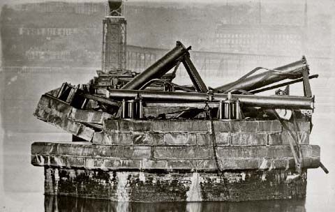
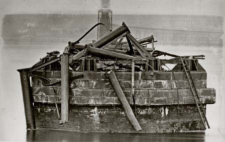
The foundations also came in for criticism, especially on those relatively few piers where the masonry had failed in the collapse, such as pier 5 (Figure 44) although not all foundations had failed like this (see Figure 45). Base bolts were found to be poorly embedded in the masonry, and the cement barely held the stones together. Some of the cement was apparently of poor quality, although there is rather little evidence of the problem. With one exception (Figure 32), the cement has broken cleanly (for example, in the column end in Figure 26, as one would expect for a brittle material.
The joints in the many tie bars however, came in for sustained critical comment. The cotters in particular, fitted the slot rather poorly, and were held only by friction of metal against metal. It could easily loosen, as was observed by Mr Noble in his many attempts to tighten them after construction. He packed them with shims. But if this was so widespread a problem, was it not an indication of a design rather than a fitment problem?