
1.1 What is finite element analysis?
Finite element analysis, utilising the finite element method (FEM), is a product of the digital age, coming to the fore with the advent of digital computers in the 1950s. It follows on from matrix methods and finite difference methods of analysis, which had been developed and used long before this time. It is a computer-based analysis tool for simulating and analysing engineering products and systems. FEA is an extremely potent engineering design utility, but one that should be used with great care. For example, it is possible to integrate a system with computer-aided design software, leading to a type of uninformed push-button analysis in the design process. Unfortunately, colossal errors can be made at the push of a button, as this warning makes clear.
Using FEA: a word of warning
Introduction
FEA is an extremely potent engineering design utility, but one which should be used with great care. Despite years of research by some of the earth’s most intelligent mathematicians and scientists, it can only answer the questions asked of it. So, as the saying goes, ask a stupid question.
The frothy solution
Current CAD [computer-aided design] vendors are now selling suites which have cut-down versions of FEA engines integrated with computer-aided design software. The notion is to allow ordinary rank-and-file designers to analyse as they design and change and update models to reach workable solutions much earlier in the design process. This kind of approach is commonly referred to as the push-button solution.
Pensive analysts are petrified of push-button analysis. This is because of the colossal errors that can be made at the push of a button. The errors are usually uncontrollable and often undetectable. Some vendors are even selling FEA plug-ins where it is not possible to view the mesh. (This is ludicrous.)
The oblivious among us may say that analysts are afraid of push-button solutions due to the job loss factor, or perhaps they are terrified of being cast out of the ivory towers in which they reside. Such arguments are nonsensical, there will always be real problems and design issues to solve. (Would you enter the Superbike Class Isle of Man TT on a moped with an objective to win, even if it had the wheels of the latest and greatest Superbike?)
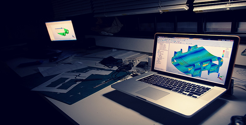
The temptation to analyse components is almost irresistible for the inexperienced, especially in an environment of one-click technology coupled with handsome and comforting contour plots. The bottom line is that FEA is not a trivial process, no level of automation and pre- and post-processing can make analyses easy, or more importantly, correct.
The analysis titan
If you have recently been awarded an engineering degree, congratulations, but remember it does not qualify you to carry out FE analyses. If it did, then a sailing course should be adequate to become Captain aboard the Blue Marlin [The world’s largest transporter vessel at the time of original publication].
This is not to say that regular engineers cannot become top rate analysts without a PhD. Some analysts have a Masters degree, but most have no more than a bachelor’s degree. The key to good analyses is knowledge of the limitations of the method and an understanding of the physical phenomena under investigation.
Superior results are usually difficult to achieve without years of high-level exposure to fields that comprise FEA technology (differential equations, numerical analysis, vector calculus, etc.). Expertise in such disciplines is required to both fully understand the requirements of any particular design circumstance, and to be able to quantify the accuracy of the analysis (or more importantly, inaccuracy) with reasonable success.
To conclude
Finite element computer programs have become common tools in the hands of design engineers. Unfortunately, many engineers who lack the proper training or understanding of the underlying concepts have been using these tools. Given the opportunity, FEA will confess to anything. The essence of any session should be to interrogate the solver with well-formed and appropriate questions.
To summarise, the most qualified person to undertake an FEA is someone who could do the analysis without FEA.
Wise words, resisting the temptation to put too much trust in FEA computer applications. If, however, computer-based simulations are set up and used correctly, highly complicated mathematical models can be solved to an extent that is sufficient to provide designers with accurate information about how the products will perform in real life, in terms of being able to carry out or sustain the operating conditions imposed upon them. The simulation models can be changed, modified and adapted to suit the various known or anticipated operating conditions, and solutions can be optimised. Thus, the designers can be confident that the real products should perform efficiently and safely, and can be manufactured profitably. A few more detailed reasons are given below.
The simulations are of continuous field systems subject to external influences whereby a variable, or combination of dependent variables, is described by comprehensive mathematical equations. Examples include:
- stress
- strain
- fluid pressure
- heat transfer
- temperature
- vibration
- sound propagation
- electromagnetic fields
- any coupled interactions of the above.
To be more specific, the FEM can handle problems possessing any or all of the following characteristics.
- Any mathematical or physical problem described by the equations of calculus, e.g. differential, integral, integro-differential or variational equations.
- Boundary value problems (also called equilibrium or steady-state problems); eigenproblems (resonance and stability phenomena); and initial value problems (diffusion, vibration and wave propagation).
- The domain of the problem (e.g. the region of space occupied by the system) may be any geometric shape, in any number of dimensions. Complicated geometries are as straightforward to handle as simple geometries, with the only difference being that the former may require a bit more time and expense. For example, a quite simple geometry would be the shape of a circular cylindrical waveguide for acoustic or electromagnetic waves (fibre optics). A more complicated geometry would be the shape of an automobile chassis, which is perhaps being analysed for the dynamic stresses induced by a rough road surface.
- Physical properties (e.g. density, stiffness, permeability, conductivity) may also vary throughout the system.
- The external influences, generally referred to as loads or loading conditions, may be in any physically meaningful form, e.g. forces, temperatures, etc. The loads are typically applied to the boundary of the system (boundary conditions), to the interior of the system (interior loads) or at the beginning of time (initial conditions).
- Problems may be linear or non-linear.