
3.3 Wired network configurations
Network nodes can be connected together in different arrangements known as topologies. We are going to describe four common topologies that you may come across.
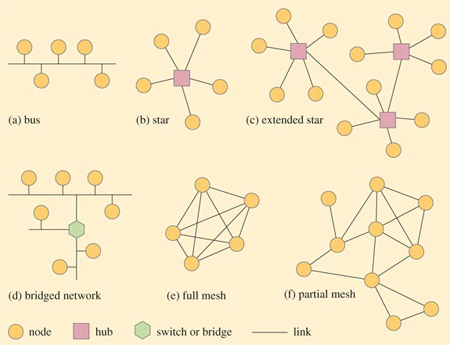
The simplest type is known as a bus topology. This is one where all the nodes connect to a single network cable and can communicate with every other attached node by placing a message onto the cable. A simplified representation of the layout of a bus topology is shown in Figure 10(a). To understand the diagram, imagine you are floating above the network and looking down. The circles represent the network nodes and the lines connecting them represent the communication links.
In a bus topology, each node connects to the same cable, so a frame sent by one node will arrive at every other node. Each node must read the destination MAC address in the frame to decide whether or not to accept it. If any node becomes inoperable, all the other nodes are still able to communicate with each other, but any cable failure will result in the loss of communication between nodes on opposite sides of the failure point.
In a star topology (Figure 10(b)) each node has its own cabled link to a central point called a hub. All messages are conveyed through the hub and, like the bus topology, will arrive at each node. In this arrangement, any single cable failure affects only one node, but a hub failure would make the entire network inoperable. Typically, the maximum number of nodes that can be connected together in a star topology is 24.
To expand a star network, hubs may be joined together so that nodes connected to one hub can communicate with nodes connected to another hub. This results in an extended star topology (Figure 10(c)).
Depending on the mode of operation, in some bus, star and extended star topologies, only one node at a time is allowed to place a frame onto the network. This means that every node has to compete with every other node for access to the network. As a network grows and traffic increases, a point is reached where competition becomes so great that the network becomes unacceptably slow.
A way of expanding the network to overcome the problems of competition is to stop sending all frames to every node and instead to separate the network into segments. A segment is a discrete portion of a network in which all nodes share the communication link. Segments are then joined together with a device known as a switch or bridge (Figure 10(d)). Such a device will examine each frame as it arrives and read the destination MAC address to establish whether or not to pass the frame onto an adjacent segment. A segment will receive only frames destined for nodes within it or frames that need to be routed through it to reach other segments further along the network. In some networks each segment could contain just a single node.
A mesh network has a web-like structure. In a full mesh topology (Figure 10(e)) each node has a point-to-point link with every other node. In a partial mesh topology (Figure 10(f)) some nodes have connections to a number of other nodes, but some may be connected to only one other node. Data between two nodes may have to travel through intermediary nodes before reaching its destination. In a partial mesh topology the nodes must have some knowledge of the network layout so that messages can be routed correctly. If a node or a communication link fails it is often possible to find another path to the destination, so mesh-type networks have high reliability.
Activity 12: self-assessment
To test your understanding of what you have read so far about wired networks, try to write down a short answer (a sentence or two) to these questions.
-
What is the term often used to describe devices connected to a wired network?
-
What is the purpose of the MAC address?
-
How does a repeater address the problem of attenuation?
-
How does a switch or a bridge make it possible to expand a network?
Answer
Answers
-
The term often used to describe devices connected to a wired network is 'node'.
-
Every node is assigned a MAC address. It is a number that uniquely identifies each node on a local area network.
-
A repeater takes a weak signal and regenerates it before passing it on.
-
A switch or bridge separates a network into segments and only passes on frames that are intended for an adjacent segment or that need to be routed through it. This means that nodes aren't competing with every other node for access to the network.