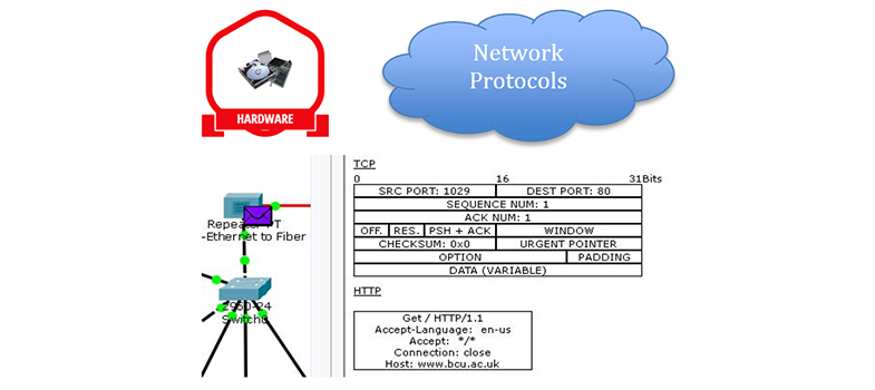
7.2.1 Switches
- Switches provide connectivity points within a network, allowing you to add a large number of devices to a network, typically using UTP cabling. Because the most common network access protocol is Ethernet, most switches will support it and are thus referred to as Ethernet switches. Ethernet switches have now largely replaced the older and much slower Ethernet hubs.
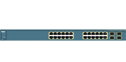
Figure 10
- Switches provide multiple Ethernet NICs, which are referred to as ports. You can use a UTP cable to connect multiple computing devices to the ports:
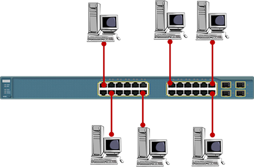
Figure 11
- The term used to describe the layout of your devices is ‘network topology’. The simple layout shown above is referred to as a star topology, as it resembles a multi-pointed star. Note that each of the UTP cables shown must be no longer than 100m.
- The number of computing devices you can connect using a single switch is limited to the number of ports that are available. If you need to add more devices, or you wish to extend the size of your network, you can connect two switches together. This topology is referred to as an extended star:
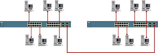
Figure 12
- The Ethernet network access protocol was originally designed to support data rates of 10Mbps. This is too slow to support modern networks, so the protocol has evolved to support greater data rates.
- Most Ethernet switches are capable of supporting several Ethernet variants on each port. Although it is possible to configure each port to operate at a particular data rate, most Ethernet switches will negotiate with the connected computing device and set themselves to the highest data rate that they both support. It is best practice to connect switches together using the fastest data rate port available.
- Switches forward data between computers using the destination MAC addresses contained in the frames they receive. This means that switches have no knowledge of the IP addresses of the packets contained within the frames, so they cannot be used to join together different IP networks. Referring to the diagram below, all the PCs are addressed within the same IP network and the switches will successfully forward data between them.
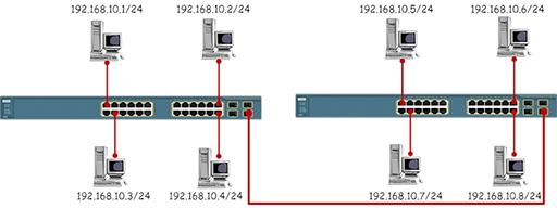
Figure 13
- The diagram below shows the same topology, but this time the PCs have been placed in different IP networks. While the switches will forward data between the PCs based on the MAC addresses in the Ethernet frames, the PCs will refuse to communicate with devices outside their own IP network.
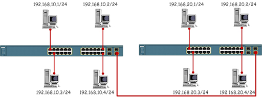
Figure 14
Activity: Data rates
Research the data rates supported by the following Ethernet variants:
| Protocol | Data rate |
|---|---|
| Ethernet | 10Mbps |
| Fast Ethernet | |
| Gigabit Ethernet | |
| 10 Gigabit Ethernet |
Interactive feature not available in single page view (see it in standard view).
Back to previous pagePrevious
7.2 Network devices