Use 'Print preview' to check the number of pages and printer settings.
Print functionality varies between browsers.
Printable page generated Wednesday, 22 July 2026, 12:16 AM
Identify network hardware and protocols
1 Layered network protocols
- Network communication relies upon the interaction of many different protocols. These protocols are designed to implement a particular set of rules and conventions governing particular aspects of how devices in a network communicate.
- Network protocols are arranged in layers, with each layer providing a specialised service for the layer above. Because each layer consists of standardised protocols that perform functions to an agreed set of rules, it is possible to modify individual protocols within a layer without having to change protocols in other layers.
- To visualise this concept of layers, consider a conversation between two people:
- Content layer: ideas exchanged in conversation.
- Rules: agree to speak a common language, take turns speaking, not to interrupt when others are speaking.
- Physical: face-to-face communication requires speakers to be close enough to hear each other.
- In this example, the conversation has been divided into three layers. The physical layer considers the fundamental requirements of exchanging information between two people using speech. This includes considering the distance between the speakers, which will affect how loud each person needs to talk in order for the other to hear. Speech is a movement of air, which is translated as sound waves. This means that the conversation could take place in a ‘near’ vacuum like outer space.
- The rules layer defines how the speakers will talk. To exchange information, a common language would need to be chosen. Once the language is agreed, how is the conversation to be managed? Taking turns is a reasonable way to converse with another person and interrupting would be considered rude. But what happens if one person misses something and wishes it to be repeated? Do they ask for it to be repeated verbally, or do they use an agreed signal such as raising a hand?
- The content layer considers the actual message exchanged between the two speakers, which in a conversation may be an item of news, plans for a holiday or just gossip.
- By dividing the conversation into layers, we have decided upon the particular functions that are required by each layer to support communication, and in our simple layered model, it should be possible to change some aspects within one layer without affecting the others. For example, if we now decide to have a telephone conversation, how does this change the requirements of our physical layer?
- Networking protocols can be layered in a similar manner to the voice conversation in the example above, but has a wider range of considerations and uses different terms:
- Encoding: language to use.
- Formatting: greeting, recipient identity, closing phrase, sender identity.
- Message size: segmentation of data.
- Timing: flow control and timeout.
- Delivery: to one host (unicast), to all hosts (broadcast), to some hosts (multicast).
2 TCP/IP reference model
- The protocols used within the Internet were designed using a layered model referred to as the TCP/IP reference model:
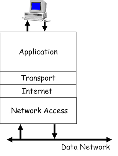
- These protocols operate on your computing devices, and allow the programs you use to access the data network via the single network interface card (NIC) that is fitted to most devices. Imagine how difficult this task would be for your device if you used multiple programs that required network access – for example, surfing the World Wide Web (WWW), downloading a file and sending an email.
- All these different programs expect to be able to simultaneously access your NIC in order to send and receive data. The purpose of the TCP/IP reference model is to allow the design and creation of protocols that can support the network requirements of various installed programs competing for the attention of a single NIC.
- Each layer of the model defines the function of the protocols that operate within it:
- Application: provides the interface between the other layers and the operating system software on your computing device.
- Transport: manages application layer data and prepares it for transmission by segmenting it into easily manageable blocks. It is also responsible for allowing multiple programs to simultaneously access the NIC, and managing the reliable delivery of data if required.
- Internet: manages the delivery of data encapsulated in packets across networks.
- Network access: manages the delivery of data across local network media, regardless of the physical media type.
- Groups of protocols that are created in accordance with a protocol model are referred to as a protocol suite. The TCP/IP protocol suite operates in accordance with the TCP/IP reference model, and it is the predominant suite used within the Internet.
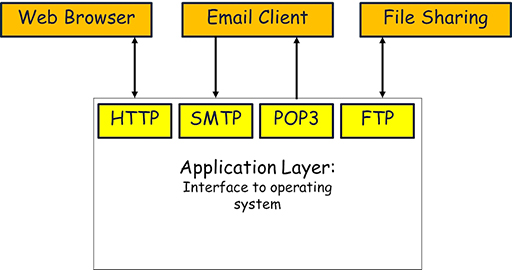
3 Application layer
- The application layer consists of many different protocols because it needs to provide an interface between the many different application programs that may be installed on a device.
- The protocols in the application layer ensure that data is exchanged between devices using an agreed format and in an agreed manner.
- Some common application protocols and the programs they support include:
- Simple Mail Transfer Protocol (SMTP): used by email programs such as Outlook and Thunderbird when they need to send emails.
- Post Office Protocol 3 (POP3): used by email programs when they need to receive emails.
- Hyper Text Transfer Protocol (HTTP): used by web browsers such as Edge and Firefox to request and transfer webpages from the WWW.
- File Transfer Protocol (FTP): often used by file sharing programs in order to send and receive files between users across the Internet.
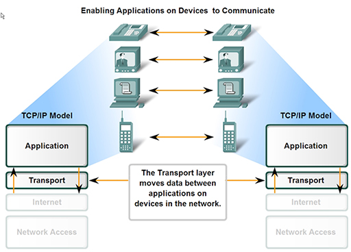
4 Transport layer
- The data from multiple application layer protocols cannot just be passed on to the lower layers in a single block, as this would lead to severe delays in sending data to the NIC.
- To visualise this problem, imagine you are heading to the till in a supermarket. Some shoppers have heavily loaded trolleys, and it takes several minutes to scan, bag and pay for all their items. Customers with fewer items use the ‘ten items or less’ queue, and although there may be more people in line, they are each served much more quickly than those in the queue for trolleys. Now imagine there is only one queue, and the customers with a few items are forced to queue alongside those with a trolley. The customers with only a few items have to wait longer to be served.
- This is exactly the same problem faced by the application layer protocols, as they all send different sized blocks of data to the NIC. FTP may try to send a file measured in megabytes, whereas SMTP may send an email of only a few kilobytes. If FTP gets its data to the NIC first, then transmission of the email is substantially delayed.
- One of the primary jobs of the transport layer is to divide all the data received from the application layer protocols into equal segments, which can then be mixed together (multiplexed) and passed to the next layer for processing. This process ensures that all protocols receive an equal share of the capacity of the device’s NIC.
- Once the data is divided into segments it needs to be tracked so that if they are delivered out of sequence, or some get lost, then steps can be taken to re-order or recover them. The transport layer thus encapsulates the segments it creates with a header, which contains sequence numbering to allow for segment tracking.
- When segments are received, they need to be placed in the correct order to recover the original data that was sent, but this takes time, and if your device is receiving segments from multiple applications it can get extremely busy and may not be able to cope, leading to data loss. To prevent this, the transport layer can implement flow control, which allows a device receiving segments to limit the number of segments that are sent to it from a transmitting device.
- The two most common transport layer protocols of TCP/IP are Transmission Control Protocol (TCP) and User Datagram Protocol (UDP).
- Both protocols manage the communication of multiple applications.
- The differences between the two centre on the specific functions each protocol implements.
- TCP provides reliable delivery of data, therefore it supports all the functions described above – segmentation, multiplexing, sequencing and flow control. The disadvantages of using TCP is that, due to its complexity, it can introduce unwanted delays between communicating devices.
- UDP provides rapid delivery of data, but without reliability. UDP only provides segmenting and multiplexing of data received from the application layer. Data from communication programs using voice and video are typically intolerant of delay and therefore use UDP.
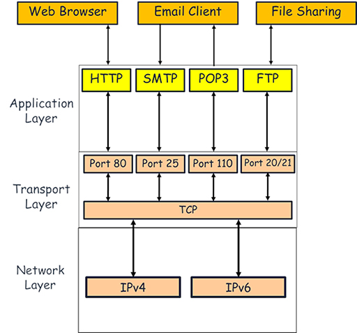
- Both TCP and UDP keep track of the application layer protocols they handle by using port numbers, which act like doorways between the transport and application layers. These range from 1 to 65535, and protocols are associated with individual port numbers:
- SMTP: port 25
- POP3: port 110
- HTTP: port 80
- FTP: ports 20 and 21
- How ports operate is slightly more complex than indicated above, as only server processes use fixed, or well-known ports. Client processes (e.g. a web browser) using HTTP will select a random, unused port. This process will be examined in more detail in a later module.
5 Internet layer
- This layer allows computing devices to exchange data across networks. It receives segments of data from the transport layer protocols and encapsulates them within packets. The packets contain address information identifying the source and destination devices, allowing packet switching devices such as routers to route them to the correct destination network.
- There are two Internet layer protocols currently in use:
- Internet Protocol v4 (IPv4): this is the most popular TCP/IP Internet layer protocol, which uses 32-bit addresses, superseding historically previous versions. The networking industry is slowly phasing out IPv4 due to the rapid growth of the Internet and the increasing demand for IP addresses, which it can no longer support. However, this will take considerable time as there are many systems and devices still dedicated to IPv4.
- Internet Protocol v6 (IPv6): this is the replacement for IPv4. It uses a 128-bit address and is capable of supporting the expected future growth of devices connecting to the Internet.
- The switchover from IPv4 to IPv6 was facilitated by the layered approach to network protocols. Because IPv6 can perform the same function as IPv4, there was no requirement to redesign the protocols above (TCP and UDP) or below the Internet layer.

Activity: Compare IPv4 to IPv6
6 Network access layer
- This layer is responsible for preparing the data packets it receives from the Internet layer for transmission to the physical media connecting devices within the local network. There are three main types of physical media available:
- Copper: coaxial, twisted pair.
- Optical: single mode, multi-mode.
- Wireless: WiFi, satellite.
- Due the wide range of media, and supported technology, the network access layer is more complex than the other layers. Additionally, while the upper layer protocols within the TCP/IP suite are implemented in software, the network access layer must provide physical connectivity, thus it has both hardware and software components, typically implemented within a device’s NIC.
- The primary functions of the network access layer are:
- Accepting packets from IP and encapsulating them within frames. Different protocols can use different types of frames.
- Converting the binary bits that make up the frame into a signal suitable for the type of media that is in use. For example, the bits are converted into an electrical signal for copper media and into pulses of light for optical media. Bits are converted to ultra high frequency radio waves on a wireless network.
- Whereas the upper layer protocols are controlled by the agencies charged with maintaining the Internet (primarily the Internet Engineering Task Force), the sheer number of physical media available has led to many different protocols being designed and produced, often by commercial organisations.
- Over time, many of these protocols have become standardised and thus have become available for general use. The most commonly used network access Local Area Network (LAN) protocol is Ethernet and its derivatives.
- The frames used by Ethernet totally encapsulate the IP packets sent from the network layer, so devices cannot directly read the IP addresses they contain. This makes it necessary for frames to carry their own source and destination addresses to ensure frames are delivered to the correct devices in the local network.
- In an Ethernet network, this address is known as a Media Access Control (MAC) address.
7 Network hardware
- A network is made up of hardware, which can be categorised as either:
- transmission media
- devices.
- Hardware devices make forwarding decisions to send data between user devices across interconnecting pathways created using copper, optical or wireless transmission media.
7.1 Transmission media
- Most home networks use a combination of copper and wireless transmission media to interconnect devices.
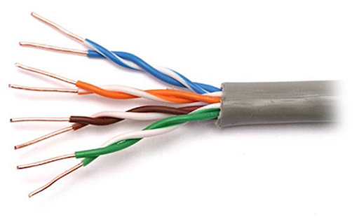
- The copper wiring normally used to support the operation of Ethernet within homes is referred to as unshielded twisted pair (UTP). This consists of four insulated twisted copper pairs within a protective outer jacket:
- The advantages of using UTP in the home is that pre-made cables are easily available, and they are cheaper than coaxial cables, which they have largely replaced.
- One disadvantage of UTP is that it is vulnerable to electromagnetic noise signals. Noise signals are created by other electromagnetic sources, such as power cables, lighting and power tools. Electromagnetic noise can appear on the UTP copper pair and interfere with the data signals it is carrying. This can lead to data loss or data corruption.
- To minimise the effects of noise, the copper pairs are twisted together, which helps cancel out noise signals travelling down the pair. Additionally, UTP cable lengths are limited to 100m when carrying Ethernet to guarantee that they can support the required data rates in the presence of noise.
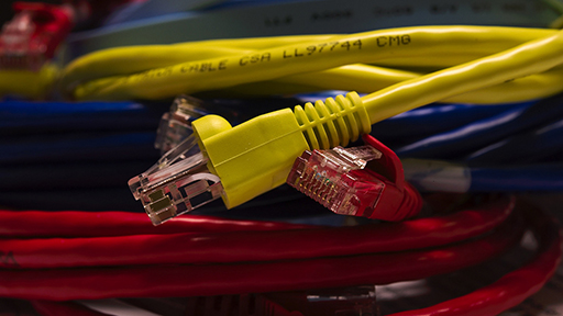
- UTP cables have to be wired correctly to allow the twisted pairs to perform noise cancellation, and this is achieved using a standard plug, called an RJ45, and a particular wiring convention. A correctly built UTP cable with an RJ45 connector can be connected to the Ethernet NIC ports of most devices:
- Wireless is a very popular transmission media within home networks, as the lack of physical cabling makes connecting new devices relatively straightforward. In a home environment, the WiFi system requires a WiFi NIC fitted to the user’s computing device, allowing it to connect to a compatible wireless access point (WAP), which will itself generally connect to the rest of the network using a UTP connection:
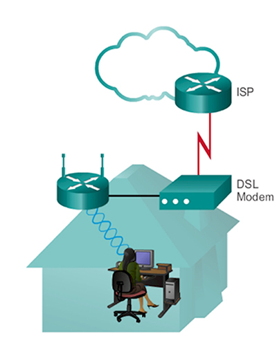
- WiFi is a popular network access technology as it is derived from Ethernet, and there are many devices available that provide both Ethernet and WiFi capability. This is especially true at home, as the ‘home router’ you use to connect to your Internet Service Provider (ISP) will provide both Ethernet and WiFi connectivity, as it contains an integrated WAP.
- WiFi wireless is also affected by noise signals, but to a far greater degree than UTP as it is impossible to protect a wireless signal from external interference. Whereas UTP will guarantee a fixed data rate over 100m, the rate achieved over wireless will steadily reduce as the user device moves away from the access point.
- WiFi introduces another serious problem, as the signal it produces does not stop when it reaches the limits of your property. This makes it possible for other people to ‘hijack’ your network by connecting to it wirelessly. It is therefore extremely important to use some form of security, such as a password, to prevent such access.
7.2 Network devices
- Networks require a variety of different devices, each with a particular function, in order to provide connectivity and data forwarding. In a home network, the router provided by your ISP will provide all these functions, but in larger networks within businesses and schools, discrete devices are required.
7.2.1 Switches
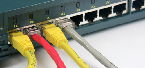
- Switches provide connectivity points within a network, allowing you to add a large number of devices to a network, typically using UTP cabling. Because the most common network access protocol is Ethernet, most switches will support it and are thus referred to as Ethernet switches. Ethernet switches have now largely replaced the older and much slower Ethernet hubs.
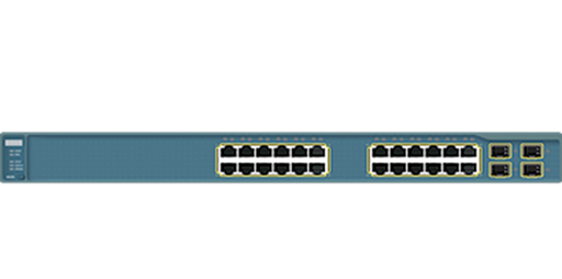
- Switches provide multiple Ethernet NICs, which are referred to as ports. You can use a UTP cable to connect multiple computing devices to the ports:
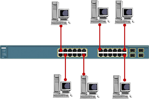
- The term used to describe the layout of your devices is ‘network topology’. The simple layout shown above is referred to as a star topology, as it resembles a multi-pointed star. Note that each of the UTP cables shown must be no longer than 100m.
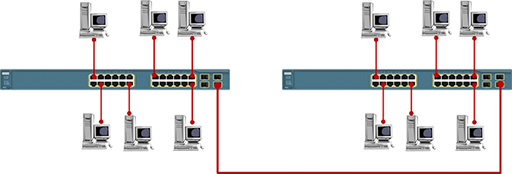
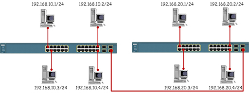
- The number of computing devices you can connect using a single switch is limited to the number of ports that are available. If you need to add more devices, or you wish to extend the size of your network, you can connect two switches together. This topology is referred to as an extended star:
- The Ethernet network access protocol was originally designed to support data rates of 10Mbps. This is too slow to support modern networks, so the protocol has evolved to support greater data rates.
- Most Ethernet switches are capable of supporting several Ethernet variants on each port. Although it is possible to configure each port to operate at a particular data rate, most Ethernet switches will negotiate with the connected computing device and set themselves to the highest data rate that they both support. It is best practice to connect switches together using the fastest data rate port available.
- Switches forward data between computers using the destination MAC addresses contained in the frames they receive. This means that switches have no knowledge of the IP addresses of the packets contained within the frames, so they cannot be used to join together different IP networks. Referring to the diagram below, all the PCs are addressed within the same IP network and the switches will successfully forward data between them.
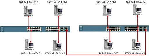
- The diagram below shows the same topology, but this time the PCs have been placed in different IP networks. While the switches will forward data between the PCs based on the MAC addresses in the Ethernet frames, the PCs will refuse to communicate with devices outside their own IP network.
Activity: Data rates
Research the data rates supported by the following Ethernet variants:
| Protocol | Data rate |
|---|---|
| Ethernet | 10Mbps |
| Fast Ethernet | |
| Gigabit Ethernet | |
| 10 Gigabit Ethernet |
7.2.2 Routers
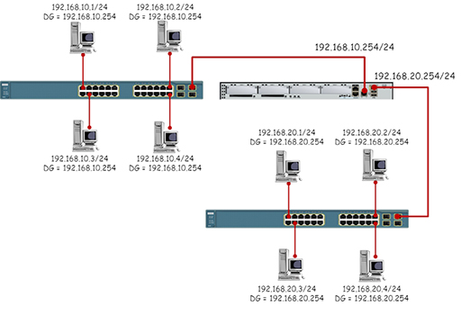
- Routers provide connectivity between different IP networks and are responsible for forwarding IP packets based on their destination IP addresses. It is the job of the router to connect many different networks – this is how the internet operates. Routers provide multiple Ethernet NICs, which are referred to as interfaces. Typical routers do not have many interfaces, as they are not designed to provide connectivity between different IP networks rather than for individual hosts.
- Each router interface must be addressed with an IP address within the network to which they connect. This IP address will act as the default gateway address configured on all the host devices within the IP network:
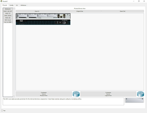
- Although Ethernet is the most common network access protocol you will meet in LANs, there are many other types of protocols available, especially within Wide Area Networks (WANs). Because routers are designed to connect networks together, they must be capable of supporting multiple network access protocols. Some routers are specifically designed to connect to particular types of WANs, whereas others are modular in design, allowing you to add the correct NIC for the WAN network access protocol in use.
7.2.3 Wireless Access Points (WAP)
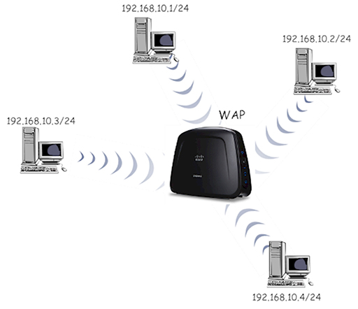
- You can send data directly between two devices using WiFi provided that the devices have compatible wireless NICs fitted. This is very useful if you wish create a temporary connection between the devices, but it can prove difficult to manage as you try to connect more devices.
- Using a wireless access point in your network provides a central WiFi connection point to which all WiFi capable devices must connect in order to exchange data. In effect, you have created a star topology without wires:
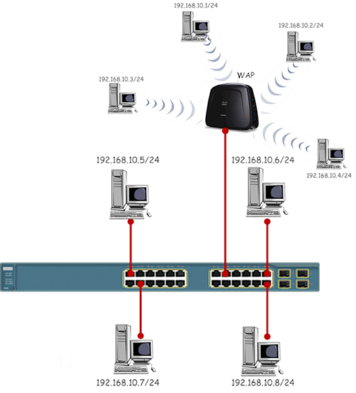
- While a single star topology WiFi network can be useful, you are more likely to meet WAPs connected to Ethernet switches, allowing the network to provide both wired and wireless network access:
7.2.4 Modem
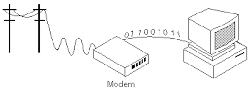
- The function of a modem is to MOdulate and DEModulate data to and from a transmission media. In the early days of the Internet, computers sent binary bits, which alternated between 0 and 5v, towards an ISP using the telephone system, which was (and still is) designed to process audio signals from telephones.
- The modem was required to convert the binary electrical signal from the computer into an audio signal suitable for transmission over the telephone system, and vice versa. So it was used to modulate data onto the phone line, and demodulate data received from the phone line:
- You will not see many individual modems in modern networks as they are now integrated within other devices, such as home routers. They are still needed as home Internet access via Digital Subscriber Line (DSL) utilises the telephone system, albeit using different frequencies. Cable Internet providers also utilise modems, as the binary electrical signal from a computer has to be converted into the radio frequencies used within the cable transmission system.
- There are also some legacy systems that still require modems, such as some older chip and pin systems. Network engineers also use modems as a secret back door into their networks, just in case the main connection fails and they need to remotely find the cause of the issue.
7.2.5 Home router
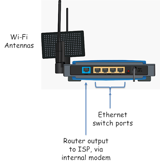
- If you have an Internet connection at home, you are probably using a home router given to you by your service provider. Although it is often referred to as a router, it is actually a combination of all the devices that we have discussed so far:
- Wireless Access Point: provides wireless connectivity for WiFi devices.
- Switch: provides Ethernet ports for the connection of devices using UTP cables.
- Router: provides routing between the home and ISP IP networks. Also performs Network Address Translation (NAT) and firewall security.
- Modem: converts the router output to a format suitable for transmission over the link used to connect to the ISP, usually DSL or cable.
8 Network address translation
- You will have read about NAT when exploring IP packet forwarding, but it is covered in more detail here.
- If you examine the diagram below, you will see that the home LAN is using IP addresses in IP network 192.168.0.0/24, which will be the case for all the ISP’s customers who are using the same type of home router. This will cause problems, as the source and destination addresses have to be unique in every communication unicast (sending packets between two devices).
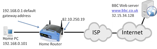
- Why do home routers use the same address on the home LAN if it will cause problems within the Internet? Remember, IPv4 cannot provide sufficient IP addresses for all the devices that want to use IP, so certain ranges of IP address, including 192.168.0.0/16, are set aside as private addresses.
- Private IP addresses can be used by anyone, at any time, within a private network. This addresses the issue of not having sufficient IP addresses, but creates a problem in that the IP address cannot be used to communicate over the Internet as it is not unique. However, you will have a unique, public IP address assigned to your home router on the interface that connects to the ISP, which in the diagram above is 82.10.250.19.
- The idea of NAT is to convert the source address from all outgoing LAN packets into the unique public address assigned to the home router, and vice versa for incoming packets from the Internet.
IP addresses in packets
- The image below shows a packet transmitted from the home PC towards the web server, which needs to be routed towards the Internet by the home router:
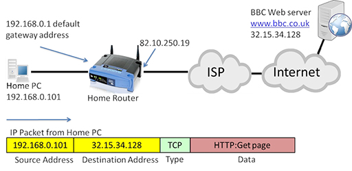
- Note that in the diagram above the source address is 192.168.0.101, which is private.
- The packet will be received by the home router, which will perform NAT, converting the source address to its own WAN interface IP address (82.10.250.19):

- The packet can now be forwarded through the Internet to the destination web server, which will return the requested webpage in a series of packets:
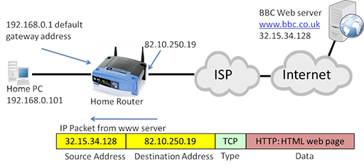
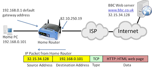
- The IP packet is now addressed with the web server acting as the source, and the public address of the home router WAN interface as the destination. The home router will accept the incoming packet, and translate the destination address back to the private IP address of the home PC:
- The use of NAT and private IP addresses has extended the life of IPv4 well beyond what would have been possible with the original range of addresses it provided. Private IP addresses and NAT are implemented within most home and business networks.
9 Using networks securely
- You need to consider the security of your home network in order to protect your personal security. If your network is not secured, or you use it in an insecure way, then you increase the risk of threats to yourself and your data.
- Consider some of the activities that you undertake via the Internet:
- emailing
- sending photographs
- chatting
- posting to wiki
- shopping
- banking.
- What would be the impact if someone was able to intercept any information you sent while doing these activities? It could range from personal embarrassment to severe financial loss. You would probably not do any of these things with a stranger sat next to you, but when you do them over the Internet, there is a risk that your data can be intercepted by others.
- What could be the motivation for trying to access your information? The list is long, but some popular reasons are:
- general nosiness
- a wish to bully or get you into trouble
- a wish to steal your money or data
- a desire to impersonate you while carrying out a criminal activity.
- To start securing your network, consider the passwords that you use to protect access to your online accounts, and to your network devices such as PCs, tablets and home routers.
- Your passwords need to be strong. Use a mix of numbers, letters and special characters. Do not use anything that could be guessed, such as a pet’s name or a birthday.
- You need to change your passwords regularly in case other people learn them.
- Do not tell your passwords to anyone. Ever.
- If you have set up a password hint, do not make the hint too obvious.
- Do not use the same password across multiple accounts and devices. If someone learns it, they have access to everything.
- Do not write your passwords down.
- You also need to consider how your devices handle your passwords, as some will try to be helpful and store them for you. If you are using a public computer to access a website that requires you to enter a password, the browser may offer to store it for you. This is not a good idea, as the next user of the computer can access your passwords.
- If you log into your account and then walk off to do something else, leaving the computer unattended, anyone else who is present can access your account. If you leave your PC or device, logout from it first. Most PCs, tablets and smartphones can be configured to automatically logout after a short period of inactivity, so find out how to set this up.
10 Malware
- Malware is a type of computer program created by criminals with the intention of stealing or damaging data and perhaps disrupting network operation. There are three main types of malware:
- Virus: malicious software attached to another program to execute a particular action on a computer. Viruses normally require the intervention of humans in order to propagate themselves, and are commonly received as attachments to emails or as files stored on USB memory sticks.
- Worms: self-contained malware programs that attack a computer and try to exploit a specific security ‘hole’ or vulnerability in a software program installed on it. Once they have successfully attacked the vulnerability, the worm copies its program across the network to attack other devices on the network.
- Trojan horse: similar in operation to a worm, except it is disguised to look like a useful software program that you may want to install on your computer. Once you have installed the Trojan, it will act as if it is normal software, but will be secretly carrying out some criminal activity such as logging the keys you are typing in an attempt to copy your passwords. Trojans are normally capable of transmitting the information they steal to interested criminals via your network connection to the Internet.
- There are many precautions you can take to protect yourself from malware:
- Always install antivirus software on your computers and make sure it is kept up-to-date.
- Always keep your operating system updated, as updates include patches for any vulnerabilities that may be exploited by malware. Most operating systems can be configured to do this automatically for you.
- Never open email attachments from people you do not know. Always scan email attachments from people you do know.
- Always scan your USB memory sticks with your antivirus software after inserting them into your computer. Never plug in a memory stick that you have ‘found’.
- Always keep copies (backups) of your important files on a separate hard drive, preferably one that is not kept connected to your network. You can then retrieve your data if malware damages the originals.
11 Phishing
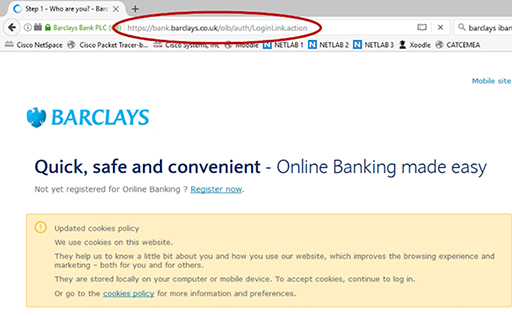
- Many criminals will try to get you to reveal passwords and other account information by pretending to be someone else. This shouldn’t be an issue if you follow the advice already covered in this course – in particular that you should never share your passwords. However, some criminals are very skilled, and send emails and texts that appear to come from legitimate sources, such as a bank or a government agency:

- These messages will normally direct you to a website, which may appear very convincing but is designed to capture all your login information. To protect yourself from phishing, remember that legitimate organisations do not conduct sensitive business via email or text – they will generally use the telephone or send a letter. When they do email, it will be a request for you to login to your account securely, so be suspicious of any links to websites that could be run by fraudsters.
- Always check the address bar of your web browser to see which application layer protocol is being used to send your sensitive information to a website. Responsible organisations will use HTTPS, which is a secure version of HTTP and can prevent your data being intercepted by Internet-based criminals:
12 Activities
Activity: Investigating your home network
Activity: Network devices and protocols – Packet Tracer
We connect our devices to the Internet and the Internet connects them all together. But what is the Internet made of? We say it interconnects all the devices, but how?
Network devices are mainly hubs, switches or routers. There are lots of other specialist bits, but the bulk of the interconnectivity is done by switches and routers. In this course you have looked at client server models, web requests and emails. What do these messages look like and how are they sent?
For each type of communication over the network there are a set of rules and specifications as to what format and order the information is sent. These are called protocols and they are fundamental in understanding how the Internet works.
This Packet Tracer lab explores the devices and protocols used in computer networks. You will need:
Activity: Password hints
Companies do not store a user’s passwords in clear text – they send it through a scrambling algorithm to produce a 'hash', and the hash is then saved. The hash algorithm does not work in reverse, so you can't unscramble a hash to get the original password. When you enter your password the site uses the same algorithm to make a hash, which it then compares to the hash saved against your details.
Some sites allow you to store password hints, and they save these as clear text. Adobe was hacked in 2013, and its hashed passwords and hints were stolen for thousands of customers. The hackers looked at all the hints that gave the same hash (hence were the same password). Because they had lots of hints for the same password it was easy to guess what they were.
Can you guess the passwords used in this puzzle based on the stolen hints?
13 Resources
For more information, take a look at the following resources.
- Watch this computer networking tutorial to explore what is a protocol:
- For a detailed look at the complexity of what happens when you click a URL read Igor Ostrovsky’s blog post.
- Read Google's guide to online safety.
- Read How-To Geek’s guide to choosing a good password and watch the following video:
- Read Action Fraud’s guide to phishing and watch the following video:
- Watch this video on being cautious when using public WiFi:
14 End of course quiz
Now it’s time to test what you’ve learned in a quiz.
15 Acknowledgements
Grateful acknowledgement is made to the following sources:
Figure 1: Birmingham City University (BCU)
Figure 2: Birmingham City University (BCU)
Figure 3: Cisco
Figure 4: Birmingham City University (BCU)
Figure 5: Birmingham City University (BCU)
Figure 6: CommScope. This file is licensed under the Creative Commons Attribution-Noncommercial-NoDerivatives Licence http://creativecommons.org/ licenses/ by-nc-nd/ 2.0/
Figure 7: tlsmith1000. This file is licensed under the Creative Commons Attribution-Share Alike Licence http://creativecommons.org/ licenses/ by-sa/ 2.0/
Figure 8: Bull3t Hughes. This file is licensed under the Creative Commons Attribution-Share Alike Licence http://creativecommons.org/ licenses/ by-sa/ 2.0/
Figure 9: Cisco
Figure 10: Cisco/Birmingham City University (BCU)
Figure 11: Cisco/Birmingham City University (BCU)
Figure 12: Cisco/Birmingham City University (BCU)
Figure 13: Cisco/Birmingham City University (BCU)
Figure 14: Cisco/Birmingham City University (BCU)
Figure 15: Cisco
Figure 16: Cisco/Birmingham City University (BCU)
Figure 17: Cisco/Birmingham City University (BCU)
Figure 18: Cisco/Birmingham City University (BCU)
Figure 19: Publisher unknown
Figure 20: Cisco/BCU
Figure 21: Birmingham City University (BCU)
Figure 22: Birmingham City University (BCU)
Figure 23: Birmingham City University (BCU)
Figure 24: Birmingham City University (BCU)
Figure 25: Birmingham City University (BCU)
Figure 26: Publisher unknown
Figure 27: Screenshot taken from Barclays, example of phishing.
Every effort has been made to contact copyright holders. If any have been inadvertently overlooked the publishers will be pleased to make the necessary arrangements at the first opportunity.