Use 'Print preview' to check the number of pages and printer settings.
Print functionality varies between browsers.
Printable page generated Thursday, 18 June 2026, 6:20 PM
Data networks and IP addresses
1 Network communication
- Communication begins with a message, or information, that must be sent from one individual or device to another. People exchange ideas using many different communication methods. All of these methods have three elements in common:
- The first of these elements is the message source, or sender. Message sources are people, or electronic devices, that need to send a message to other individuals or devices.
- The second element is the destination, or receiver, of the message. The destination receives the message and interprets it.
- The third element, called a channel, consists of the transmission media that provides the pathway over which the message travels from source to destination.
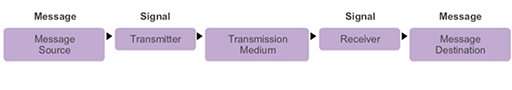
- Consider, for example, communicating a message using words, pictures and sounds. These can be sent across a data or information network by first converting them into binary digits, or bits. The bits are then encoded into a signal that can be transmitted over the appropriate medium. In computer networks, the media is usually a type of cable, or a wireless transmission. A transmitter is used by the message source to place data onto a transmission media. A receiver is used by the message destination to recover data from the transmission media.
- The term ‘network’ in this course refers to data or information networks capable of carrying many different types of communications, including traditional computer data, and interactive voice, video and entertainment products.
- Traditionally, the sources and destinations within information networks were computers, but today there are a wide range of devices capable of exchanging data:
- smart phones
- tablet computers
- cars
- domestic appliances.
- The transmission media can be either guided or unguided.
- Examples of guided media include wired technology such as:
- coaxial cable (e.g. cable TV systems)
- unshielded twisted pair (e.g. DSL broadband)
- fibre optic (e.g. high speed cable systems).
- Examples of unguided media include wireless technology such as:
- WiFi (e.g. home network)
- cellular (e.g. 3G, 4G, 5G mobile phones)
- satellite (e.g. television).
- The media chosen will determine the type of transmitter and receiver required.
2 Network addressing
- When a ‘message’ such as a file, image or video is transmitted across a network, it is first broken down into small blocks called segments. These are placed into containers called packets, typically by the Internet Protocol (IP). There are two versions of IP: version 4 and version 6.
- IP is responsible for delivering the packets from source to destination, and regardless of the version being used, packets must use some form of addressing to uniquely identify the message source and message destination.
- This is very similar to the way that you address a letter that you send through the post. When you send a letter, you normally write the address of the recipient (destination) on the front and your own address (source) on the back.
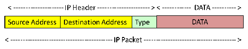
- IP includes other information within the packets, including its size, and some information about the type of data that the packet contains (e.g. webpage, email).
- The information added to the data to create the packet is called the IP header. The process of adding the IP header to the data is called ‘encapsulation’.
- Encapsulation is a complex term used to describe a simple technical process. Think of presents you may be given for your birthday – they are encapsulated in wrapping paper. So, encapsulation is the thin, additional layer of information used to wrap around data when it is sent between computers.
- Continuing the birthday present analogy, many of you may have sometime in the past played pass the parcel – a children’s game involving a present that has many layers of wrapping. Similarly, networking has many layers of wrapping, or encapsulation, which are each used to help in the reliable transmission of data.
3 IPv4 address structure
- IP and postal addresses are considered to be hierarchical, which means they contain a structure. Consider a letter with the following postal address:
Mr Weyland
32 Colony Avenue
Hicksville
LV426
- The address identifies the house, street and town that the postal service needs to use to deliver the letter. It also identifies the person in the house for whom the letter is intended. This is very important, as the house probably contains a number of people and they need to be able to determine who the letters is for.
- Now consider an IPv4 address: 192.168.10.10
- The address identifies the network that the packet has to be delivered to using the ‘192.168.10’ portion of the address.
- The identity of the device, or host, within the network for which the packet is intended is ‘.10’.
- Therefore, we can say that an IPv4 address contains a network and a host component.
- Because IP addresses are designed to be used by computing devices, they are actually 32-bit binary numbers, which are converted to decimal to make them easier for people to work with. To make the addresses even easier to work with, they are divided into four 8-bit blocks called octets:
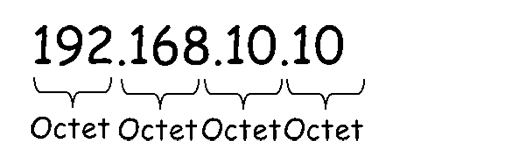
- The decimal numbers within each octet can range from 0 to 255.
Activity: Decimal and binary numbers
You need to be comfortable with converting between decimal and binary numbers. Try using the excel spreadsheet to convert the following decimal numbers into binary.
| Decimal | Binary |
|---|---|
| 2 | |
| 4 | |
| 8 | |
| 10 | |
| 24 | |
| 32 | |
| 48 | |
| 64 | |
| 128 | |
| 160 | |
| 255 | |
| 192 | |
| 168 |
- In the example above we used colour to identify the network and host components in the IPv4 address, but this technique will not work for computing devices. Instead IP subnet masks are used. The IP subnet mask is a 32-bit binary number, and each binary ‘1’ is used to identify a network bit within the IP address itself:
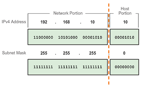
- Note that the subnet mask bits are set to ‘0’ to identify the host portion of the address. A computing device will evaluate the IP address and subnet mask together, bit by bit (this is called bit wise), performing a logical ‘AND’ operation:

- The AND function will take two inputs, and if they are both ‘1’, it will output a ‘1’. Any other combination of inputs will result in a ‘0’ output.
Example: AND function
Try performing the AND function on the address and mask shown below:
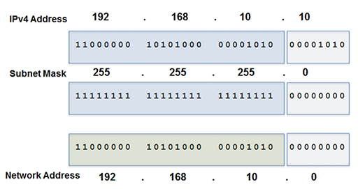
- Proceed from left to right, taking 1 bit from the address, 1 bit from the mask and perform the AND function. The output will be the network address:
- Note that the network address is 192.168.10.0, not 192.168.10 as shown previously in the coloured example. This is because the network address has to be 32-bits long, but as it does not include any host information, the host component is set to the all zero condition.
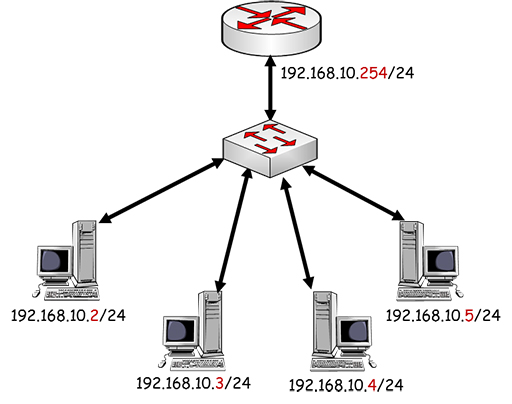
- Now that you have determined the network address, you can assign individual host addresses to the devices in your network:
- Note that all the PCs in the figure above share the same network address, but have unique host addresses. The range of possible host addresses is limited by the number of binary bits within the host octet, so in theory the range is .1 to .255. However, the .255 address is reserved for broadcast transmission, when devices need to communicate simultaneously with every host in their network, and cannot be assigned to an individual host. Thus, in this example, the range of possible host addresses is .1 to .254.
- You may have noticed that each device’s address is followed by /24. This represents the subnet mask, which we have seen is very important as it defines which parts of the address relate to the network and host components.
- Writing the subnet mask out in full (255.255.255.0) can be quite repetitive, so instead, you can state the number of bits within the mask that are set to ‘1’. As 255 corresponds to 11111111 in binary, you have eight binary bits set to ‘1’ in the octet. With three octets set to 255, you have a total of 24 bits sets to ‘1’, thus the subnet mask (or prefix length) can be written as /24.
4 Assigning IPv4 addresses
- Devices need to be configured with an IP address before they can send and receive data on a network. There are two ways of achieving this:
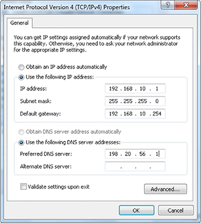
- Manual: you access each device and assign an appropriate IP address and subnet. This can be useful if you need an IP address that never changes, and is typically assigned to devices such as servers and printers. However, if you have many devices, manual configuration can be time consuming and prone to errors.
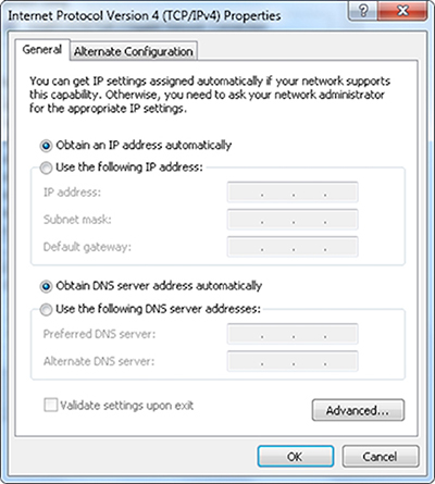 Figure 9
- Dynamic: you can employ the client/server Dynamic Host Configuration Protocol (DHCP) to automatically assign IP addresses to clients as they join the network. Only the DHCP server needs to be configured with an appropriate pool of IP addresses, which it will assign to client devices as they join the network, ensuring that the addresses are unique. DHCP is very useful when the network has many host devices and reduces the chance of errors in assigning addresses.
5 Using DHCP at home
- Most large businesses and schools will use a dedicated server to provide DHCP services, but in smaller networks the DHCP service is integrated within existing devices.
- At home, your broadband or cable router will be providing DHCP services for all the devices within your house. It does not normally require configuration, although you can access the settings and make changes if required.
- Your home router needs to provide connection to two networks:
- The Local Area Network (LAN): the network that contains all the devices within your house, such as computers, tablets and smart phones.
- The Wide Area Network (WAN): the network connecting to your service provider.
- For more information on LANs and WANs watch the following video.

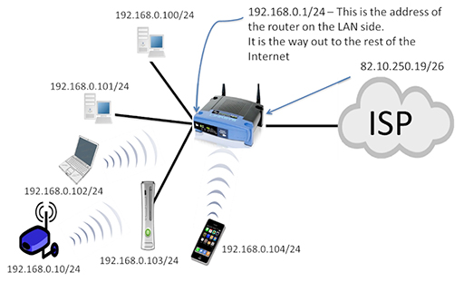
- If you examine the network in the figure above, you can see that all the household devices are part of the 192.168.0.0/24 LAN, and have received these addresses from the home router via DHCP. The home router also has an IP address within the LAN (192.168.0.1/24) – this is pre-configured by the device’s manufacturer, although it can be changed if required.
- The home router also has an IP address assigned to the interface connecting to the ISP WAN. Note that this is in a completely different network (82.10.250.19/26). The home router will forward all the data packets from the LAN towards the ISP via the WAN interface to allow you to access Internet services.
- It is important for the devices in your LAN to know when they are sending packets to other networks. They achieve this by comparing their configured network address with the destination IP address of the packet they are sending. If the two addresses are in different networks, then the device will send the packet towards the home router’s LAN interface, which is referred to as the default gateway. The home router will then forward the packet onto the ISP via its WAN interface.
- The LAN devices learn about the default gateway via DHCP.
- The WAN interface of the home router can also be assigned via DHCP, but this time the server is located in the ISP’s network, and it will assign a unique IP address to each customer, as shown above.
- If all the ISP’s customers are using the same type of home router, then all the LAN devices will be receiving IP addresses via DHCP. This means that LAN devices will not have unique addresses. This is a problem when using the Internet, as all sources and destinations must be uniquely addressed.
- This problem is solved by a process called Network Address Translation (NAT), which is performed by the home router. Packets received by the router from LAN devices will have their non-unique source addresses changed to a unique WAN interface IP address.
6 Using DNS at home
- When you are accessing the WWW from home, you may not be aware that you are using IP addresses because you normally access webpages using Uniform Resource Locators (URLs).
- However, all the packets that are exchanged between your home device and the web server require IP addresses to ensure that they are delivered correctly, so the Domain Name Services (DNS) is required to map between URLs and IP addresses.
- DNS servers contain these mappings between IP addresses and URLs. Thousands of DNS servers, spread across the world, are required to support the operation of the Internet.
- In order for your local LAN device to access DNS, it must know the IP address of the DNS server that the local ISP wishes it to use. Once again this information is learnt dynamically using DHCP.
7 Data networks and packet switching
- You have seen that data packets are responsible for transferring data across networks, and require IP addresses to do so. The box below describes in more detail how a PC uses packets to retrieve a webpage (without considering the action of NAT).
How a PC uses packets to retrieve a webpage
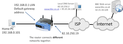
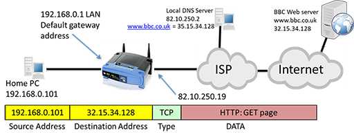
- The user within the home LAN enters a URL such as www.bbc.co.uk into the browser on their PC, which has an IP of 192.168.0.101. The PC then creates an IP packet addressed to the local DNS server, as it needs to resolve the correct IP address for the BBC web server:
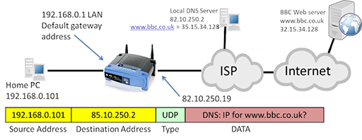
- The packet uses the IP address of the home PC as its source and the IP address of the DNS server as its destination. The packet contains a request from the DNS for the IP address of the BBC web server. Note that the ‘type’ field of the packet identifies the User Datagram Protocol (UDP), which is responsible for segmenting the DNS request so that the IP can encapsulate it within a packet.
- The PC identifies that the packet is leaving the LAN, as the source and destination networks are within different IP networks, so it forwards the packet towards the default gateway it has learnt via DHCP: 192.168.0.1, which is the LAN interface of the home router.
- The router examines its routing table, which identifies all the IP networks the router can forward packets to. It is then able to identify an exit interface to use in order to forward the packet towards the destination network identified in the packet.
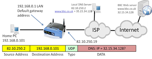
- The packet may be required to pass through multiple routers, but it eventually arrives at the DNS server, which examines the DNS request and identifies the IP address that maps to the URL. It then creates a new packet containing a response, which is forwarded back to the home PC:
- The packet returns to the home router, which forwards it to the PC. The PC now has the correct IP address for the URL it wishes to contact, so it can construct a new packet containing the web server as a destination and carrying an HTTP GET message requesting webpage content. Note that the protocol type has changed to Transmission Control Protocol (TCP). Like UDP it performs segmentation, but also provides reliability mechanisms to protect against data errors if packets are lost or damaged during transmission.

- Once again, the PC realises that the packet’s destination is not on the local LAN and forwards it to the home router, which in turn forwards the packet to the ISP and onto the Internet via its WAN interface. The packet passes through several routers as it heads towards the web server, with each router checking the destination address within the packet and forwarding appropriately.
- Once the web server receives the packet, it examines the GET message to see which particular page is required, and then returns the webpage as HTML within a series of packets addressed to the home PC:
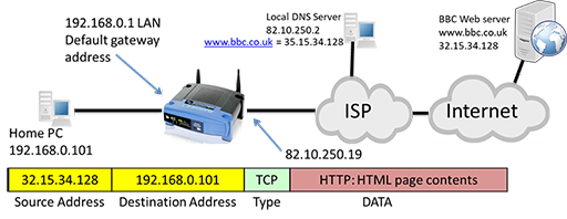
- The process explained above is facilitated by routers within both the home network and within the Internet itself. Routers forward packets based on the destination address they find in the IP packet header, and the information they themselves know about how to reach the identified destination.
- Routers store information internally about destination networks in tables called ‘routing tables’. The process of accepting a packet on an incoming interface, making a decision on what to do with it, and then sending it towards another interface is called packet switching. To learn more about packet switching watch the following video.
- The networks which make up the Internet are complex, and there are often multiple different paths that routers can use to packet switch towards a destination. When faced with multiple paths, routers are capable of deciding which path to choose based on a variety of network characteristics, a process known as routing.
8 Activities
Activity: Tablets of stone – network communication protocols
Complete the classroom activity provided in the activity book, Tablets of Stone, which simulates a network distributing messages. It explores how information is added to messages to ensure they are sent to the correct recipient, and looks at how this makes up a protocol.
Activity: Setting up the home network, IP and packet switching (Packet Tracer)
For most of us, internet connectivity starts in the home or school. This Packet Tracer lab is in several parts and explores IP addressing and packet switching in turn.
You will also need
9 Additional resources
For more information on the subjects covered in this course, download the Digital Schoolhouse’s publication on Communications and Networks Unplugged. You can register for free with the Digital Schoolhouse to access the resources needed for the activities it includes. The following activities are particularly relevant to this course:
- 2. Understanding how data travel through the internet (page 16)
- 3. Data transfer protocols (page 19)
- 4. Packet switching (page 25)
- 5. Understanding IP Addresses as unique identifiers (page 29)
- 6. The Binary behind IP Addresses (page 35)
- 10. How search engines rank the webpages into an order (page 49)
10 End of course quiz
Now it’s time to test what you’ve learned in a quiz.
11 Acknowledgements
Grateful acknowledgement is made to the following sources:
Figure 1: Cisco
Figure 2: Birmingham City University (BCU)
Figure 3: Birmingham City University (BCU)
Figure 4: Cisco
Figure 5: Birmingham City University (BCU)
Figure 6: Cisco
Figure 7: Birmingham City University (BCU)
Figure 10: Birmingham City University (BCU)
Figure 11: Birmingham City University (BCU)
Figure 12: Birmingham City University (BCU)
Figure 13: Birmingham City University (BCU)
Figure 14: Birmingham City University (BCU)
Figure 15: Birmingham City University (BCU)
Figure 16: Birmingham City University (BCU)
Figure 17: Birmingham City University (BCU)
Every effort has been made to contact copyright holders. If any have been inadvertently overlooked the publishers will be pleased to make the necessary arrangements at the first opportunity.