Use 'Print preview' to check the number of pages and printer settings.
Print functionality varies between browsers.
Printable page generated Sunday, 26 July 2026, 7:03 AM
The purpose of network hardware and protocols
1 Layered network protocols
- Network communication relies upon the interaction of many different protocols, which implement the rules and conventions governing how devices in a network communicate. These protocols are designed and implemented through a layered approach, which allows us to modify individual protocols to accommodate technological changes without impacting the operation of protocols in the layers above and below.
- Using a layered network protocol reference model also makes it much easier to understand the underlying function of the individual protocols, and how they relate to protocols in other layers.
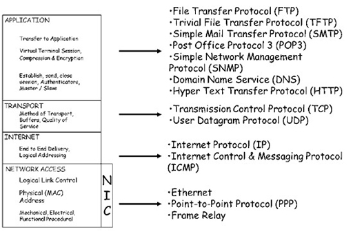
- Remember that a reference model is a way of understanding the interrelation between protocols, and cannot support network communication. Network communication is supported by protocols that are compliant with the reference model – these are referred to as a suite of protocols. When an operating system is installed on a computing device, it will install a variety of Transmission Control Protocol (TCP)/User Datagram Protocol (UDP) protocols that are capable of supporting network communications.
- You have seen in previous work that the programs on a computing device pass data to the TCP/IP protocols when the data needs to be transmitted across a network connection. The data is accepted by the application layer, before being passed to the transport, Internet and network access layers. Each layer adds additional information called a header in a process called encapsulation. The header provides additional information that allows the encapsulating protocol to perform its required functions. The addition of header information creates a Protocol Data Unit (PDU), and each layer has an identifiable PDU:
- transport (TCP): segment
- transport (UDP): datagram
- Internet: packet
- network access: frame.
- Note that the two transport layer protocols have different names for their PDUs, indicating the slight differences in function between them.
- Data that is received from the network media is passed back up through the TCP/IP layers. Each layer interprets the header information in the PDU that it is interested in, before passing the data to the layer above. Once the information within a header has been interpreted, the header is discarded, revealing the PDU for the next layer. This process is referred to as de-encapsulation.
2 Transport layer – TCP
- TCP is a reliable transport protocol, and performs processes to ensure reliable delivery of data between applications using acknowledged delivery. An analogy for the operation would be ordering some items online for delivery to your home. You will be able to track the progress of the packages while they are in transit, and you may be required to sign for them, which provides acknowledgement of their delivery. You will also be able to contact the seller of the items if any are not delivered to arrange for re-delivery.
- The four basic functions of TCP are:
- Ensuring data segments are delivered in the correct sequence to the correct application layer protocol.
- Providing flow control, so segments are delivered at a rate the receiving device can handle.
- Multiplexing of multiple user applications, allowing them to simultaneously access the transmission network.
- Error checking received segments, and requesting retransmission if segments have been corrupted.
- TCP breaks up data received from the application layer into small pieces known as segments. To provide reliable transmission, the segments are numbered before being passed to the IP process, which encapsulates them into packets. TCP tracks the number of segments that are sent to a specific destination device from a specific application layer protocol. If it does not receive acknowledgement within a certain period of time, TCP assumes that the segments have been lost and will retransmit them.
- TCP also checks each segment to ensure that the contents have not been changed during transmission across the network media. This process is referred to as error checking, and is possible because each segment header includes a check-sum, which is a mathematical signature generated by feeding the data in the segment through a cyclical redundancy algorithm. This is placed in the TCP header by the sender, and the receiving device will carry out the same calculation on the data in the received segment. If the signatures match, TCP will consider the data within the segment as not damaged. If the signatures do not match, TCP will arrange for the data to be retransmitted.
- TCP can serve multiple application layer protocols simultaneously, processing their data into segments and feeding them to the Internet layer in a process called multiplexing. To allow TCP to deliver received segments to the correct application layer protocol, port numbers are used.
- Because TCP may receive a significant number of segments, which need to be error-checked, sequenced and delivered to the correct application layer protocol, it needs to be able to control the amount of segments it receives to allow it to operate effectively. A TCP receiving process will agree a window size with a TCP sender, which dictates the amounts of segments that can be sent before a TCP acknowledgment is sent by the receiver. The TCP receiver can thus control the amount of segments it is sent, a process called flow control.
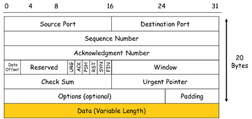
- The diagram above is a graphical representation of a TCP header, which is divided into a series of areas called fields. The numbers across the top indicate the length of each field in bits. The total size of the header is 20 bytes. This header is added to the segment of application data, shown as the orange data field at the bottom. This is referred to as the payload of the segment, and can be a maximum of 1460 bytes.
Activity: Fields in a TCP header
In the diagram above showing the representation of a TCP header, identify the fields that allow TCP to carry out its main function:
Two lists follow, match one item from the first with one item from the second. Each item can only be matched once. There are 4 items in each list.
-
sequencing
-
flow control
-
multiplexing
-
error detection
Match each of the previous list items with an item from the following list:
a.check-sum/acknowledgement
b.sequence number
c.window/acknowledgement
d.source/destination port
- 1 = b,
- 2 = c,
- 3 = d,
- 4 = a
3 TCP three-way handshake
- Because of the complexity of TCP operation, it needs to perform a three-way handshake to exchange sequence numbers prior to sending any data segments:
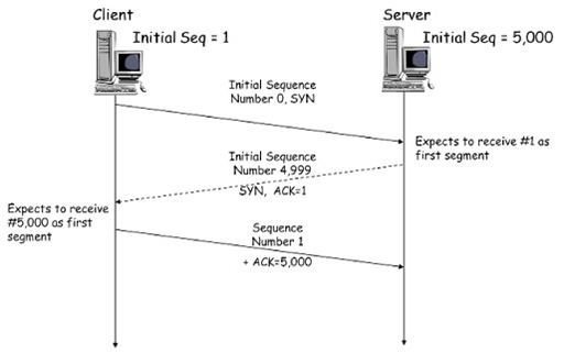
- The diagram shows the timeline of TCP information exchanged between a client device and a web server within a three-way handshake. The client selects a random number that represents its initial sequence number. (In the example above this is ‘1’, but in reality the number would be very large.) The client subtracts 1 from the initial sequence number (making it 0) and sets the SYN (synchronise) flag to ‘1’. You can see the SYN field in the TCP header diagram above: it is 1 bit in size. This information is sent to the web server in a short segment, without any application layer data.
- The server accepts the segment, noting the sequence number is ‘0’. The server recognises that this less than the client’s initial sequence number by 1, so it sets the sequence number for the client to ‘1’. It returns an acknowledgement number of ‘1’ back to the client in a short segment, with both the SYN and ACK (acknowledge) flags set to ‘1’. Note that the server has also picked an initial sequence number of 5000, which it reduced by 1 and sent within the ACK segment.
- The client receives the ACK segment and recognises that the server chose an initial sequence number of 5000. The server acknowledges this with an acknowledgement number of 5000 and sets the ACK flag to ‘1’. Both devices now know the initial sequence numbers each will use as part of their TCP exchange.
4 TCP windowing and flow control
- Although not shown in the figure describing a TCP three-way handshake, both the client and the server will also have exchanged window size information during this process to set the maximum amount of data that can be sent without acknowledgement.
- A simplified windowing process is illustrated in the figure below. In a real TCP exchange, both the client and server would send data and windowing information, but for clarity only the server window size is shown.
TCP windowing and flow control process
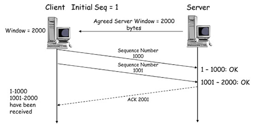
- In the figure above, the TCP three-way handshake has been completed and the server has informed the client that it will only accept 2000 bytes of data prior to sending an acknowledgement.
- The client sets its initial sequence number to ‘1’ and starts to send data segments to the server. The first segment contains 1000 bytes and is sent with a sequence number of ‘1’. This is received by the server, which examines the check-sum to ensure that the segment is error-free. If it is the server will accept the segment.
- For the next segment, the client increases the sequence number to ‘1001’ by adding the number of bytes in the previous segment (1000). The client sends this to the server, which again ensures that it is error-free. Because the server has set a window size of 2000, the client cannot send anymore segments without the server acknowledging those it has received.
- The server sends a segment with the ACK flag set and the next expected sequence number (2001) as the acknowledgement number. This is interpreted by the client as confirmation that the two segments it sent have been successfully received, and it is now free to send more segments up to the limit of 2000 bytes.
- The windowing process allows the server to control the flow of segments it receives during a TCP transaction. If the server had been overwhelmed with segments from other clients, then it could have delayed sending acknowledgements, thus preventing the clients from sending more segments.
5 TCP reliability
- Sequence numbers are also used by TCP to ensure that data is delivered reliably. The diagram below shows the same client and server exchange with a window size of 2000. However, the second segment, sequence number 1001, is lost during transmission and is not received by the server:
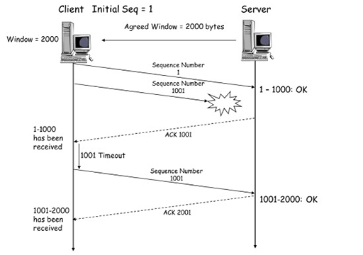
- The server will send an ACK segment to the client, with a sequence number of 1001. The client will interpret this to mean only the first segment, with sequence number 1, has been successfully received by the server. The client will now wait a short timeout interval, in the hope a delayed ACK will be received from the server confirming the receipt of 1001. If this is not received, the client will retransmit segment 1001, and await the ACK with sequence number 2001 from the server, confirming its receipt. The same procedure is followed for segments that are received with checksums indicating the presence of errors.
6 Transport layer – UDP
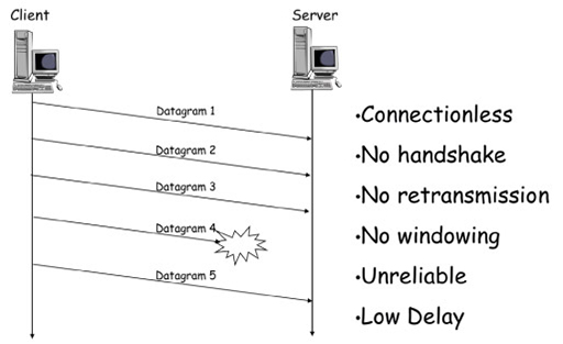
- UDP is a lightweight transport layer protocol that offers the same data segmentation and reassembly services as TCP, but without TCP’s reliability and flow control mechanisms. The advantage of using UDP is that it can rapidly send data through the transport layer without the delays that are introduced by TCP’s reliability mechanisms. This is important for real-time programs, such as voice and video services, which work best with minimal delay between communicating devices.
- UDP does not use sequence numbers or windowing, so there is no need for a three-way handshake to set initial values. If a device using UDP becomes swamped by an excessive number of datagrams, it will simply drop those that it cannot process.
- Because UDP does not use sequence numbers, it is unable to re-order datagrams that it receives in the wrong order.
- Although we talk about UDP segmenting data, the PDUs it creates are referred to as datagrams to differentiate them from TCP segments:
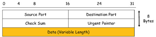
- The image above illustrates a UDP datagram header, which is very simple when compared to the TCP segment header shown earlier. It is also much smaller, containing only 8 bytes of data. This is a factor in reducing the delay of processing UDP datagrams. The only field it shares with TCP headers are the source and destination port fields, which are used to identify the application layer protocol being supported, and a check-sum field for detecting data errors in received datagrams.
7 Transport layer – ports
- The transport layer must be able to separate and manage multiple application layer protocols, which may themselves open many individual sessions. For example, when you open multiple tabs in a web browser to view multiple webpages, the application layer protocol HTTP creates a separate session for each tab.
- At the same time as viewing multiple tabs you may also send email, instant messages and download files. Each of these activities requires an application layer protocol to establish simultaneous access to the network via the transport layer protocols TCP and UDP. The transport layer protocols need to track this activity and ensure that received data is directed to the correct application layer protocol otherwise, for example, webpage data may be directed towards an email application.
- TCP and UDP manage these multiple processes by using unique port numbers contained within the header field. They add the unique port numbers to the PDU created when encapsulating application layer data into segments and datagrams, respectively.
- Application layer protocols have different requirements from the transport layer. Some require reliable delivery of data (e.g. HTTP, FTP), whereas other require a low-delay service (e.g. DNS). Different application layer protocols are designed to operate with either TCP or UDP based on these requirements.
- This link between the application and transport layer protocols is based on the ports selected to support the individual sessions supported by the transport layer. There are 65,535 port numbers available, and these are divided into three ranges:
- Well-known ports (0 to 1023). These are reserved, and are commonly used by HTTP, SMTP, POP3, FTP, DNS, etc. Because they are reserved, client applications can be programmed to request a connection to a specific port and its associated transport layer service (TCP or UDP).
- Registered ports (1024 to 49151). These are assigned to user processes or applications, typically programs that you have chosen to install on your computer that require network connectivity (e.g. games and messaging services). When not assigned to a particular installed program, they can be used in the same manner as dynamic ports.
- Dynamic or private ports (49152 to 65535). These are assigned dynamically to client applications when the client initiates a connection to a service.
- You can find a current list of port numbers and the associated applications on the Internet Assigned Numbers Authority (IANA) website. This organisation is responsible for managing a variety of Internet related matters, including ports and IP addresses.
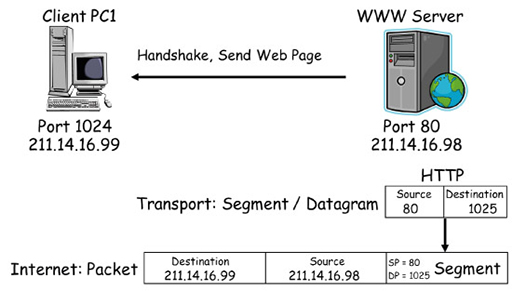
Source and destination ports in transmitting data
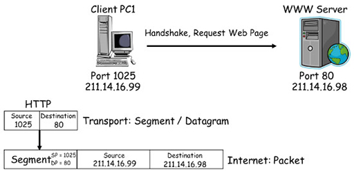
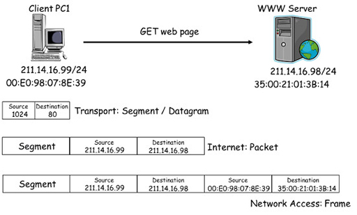
- In the diagram above, client device PC1 initiates a connection to the WWW using HTTP. HTTP selects a source port of 1025 from the registered range, which it uses to send and receive data to and from the transport layer. It also chooses a destination port of 80 from the well-known range, which the web server will be monitoring by default for incoming HTTP requests.
- Because HTTP requires reliable delivery of data, TCP on PC1 is chosen to support the connection, as it is coded to relate destination port 80 with HTTP. TCP encapsulates the HTTP request with a header containing sequencing, acknowledgment and windowing information, and performs a three-way handshake with the WWW server. The segment is encapsulated in an IP packet for forwarding across the network. In the diagram below note the destination and source addresses that are used.
- The WWW server establishes a TCP connection to the client and communicates with the local HTTP process to send the webpage the client has requested. It uses a source port of 80 (because it is a server), and a destination port of 1025, which it now knows PC1 is using to support HTTP. Once again, it is the well-known port of 80 that links HTTP to TCP, and the reliable transport service that it provides.
- You can see the same exchange in the diagram below, which shows the TCP/IP protocol stack for client PC1 and the WWW server devices:
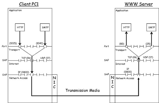
- HTTP on PC1 accesses the transport layer via registered range port 1025. Because port 80 has been chosen as a destination port, TCP is used to segment and encapsulate the HTTP data before passing it to the Internet layer protocol IP. The IP protocol encapsulates the TCP segment, adding source and destination IP addresses to create a packet, which is passed to the network access layer. If we assume the client is using an Ethernet network interface card (NIC), the Ethernet protocol will encapsulate the packet, adding source and destination media access control (MAC) addresses to create a frame.
- The resulting frame is sent to the WWW server, where the reverse process, or de-encapsulation, takes place. The frame is received by the NIC, which recovers the packet it contains and hands it to the IP. The IP recovers the segment from the packet and passes it to TCP, which uses the destination port to deliver it to HTTP.
- In the description above, you can see that PC1 is also sending an email to the WWW server. Note that it selects another registered range port, 1041, as a source for the local SMTP process, and well-known port 25 as its destination.
- The WWW server is also running an email server process, which by default monitors well-known port 25 for incoming email requests. Because of the way TCP is coded, it will accept this connection based on the well-known port being used.
- Because PC1 is running web browser and email software, every time you open a new browser tab or send an email it selects different registered range source ports. This allows the local TCP process to track the multiple application layer services it is supporting.
- As the WWW server is a server, it will always associate application layer protocols with the well-known ports assigned to them by IANA. Thus, the WWW server can support multiple client PCs via a single well-known port.
- You may be wondering why the WWW server is able to communicate with multiple devices via a single port. This is because all clients have a unique IP source address, which can be combined with the source port they have chosen to form a socket. In our example, PC1 has an IP address of 211.14.16.99, and is using source port 1025. This results in a socket of 211.14.16.99:1025, which will uniquely identify PC1 to the WWW server.
8 Internet layer – IPv4
- The Internet layer is responsible for exchanging packets over a network between identified end devices. The two most common protocols within the Internet layer are IPv4 and IPv6.
- Both protocols provide devices with a unique IP address to allow for packet delivery. You have seen previously that the growth of the Internet means that IPv4 can no longer support unique addresses for every device that requires Internet access, so Network Address Translation (NAT) is used to ‘hide’ non-unique private IP addresses behind unique public IP addresses.
- Both IPv4 and IPv6 provide a protocol with an independent means of transferring packets across networks. This means that neither is interested in the contents of data it receives from the transport layer (TCP or UDP) for encapsulation within IP packets. Nor are they interested in the network access protocol used within a local network segment – they will work equally well over wired Ethernet or wireless WiFi.
- IPv4 can receive either TCP segments or UDP datagrams from the transport layer, which it encapsulates within packets. The encapsulation process adds a header containing various fields required for the operation of IP:
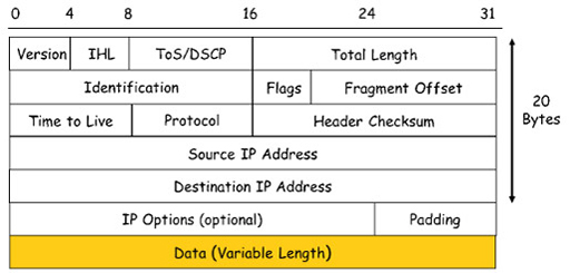
- The image above shows the many fields that make up an IPv4 header. The important fields to note are:
- Source address: the 32-bit address assigned to the NIC of the host that created a packet.
- Destination address: the 32-bit address of the device to which the packet is sent. This field is used by routers when they make a packet forwarding decision.
- Data: this is the payload that an IP carries, typically a segment or datagram from the transport layer. The payload can vary in size, but should not exceed 1480 bytes.
- Protocol: this is the identity of the transport layer protocol encapsulated within the packet. Protocols are identified using a service access point (SAP) number, which is 06 for TCP and 17 for UDP. Because the SAP of the transport layer protocol is identified in each packet, IP can deliver segments to the correct transport layer protocol on the receiving device.
- Header check-sum: this allows IPv4 to determine if the header has been damaged during transmission. If IPv4 discovers a damaged header, the entire packet is dropped. Because IPv4 does not guarantee reliable delivery of packets, it relies on TCP to arrange for retransmission of the segment encapsulated within the dropped packet.
- Time to live (TTL): provides a lifetime for each packet, which if exceeded will cause the packet to be dropped. The actual value initially placed in the TTL field depends on a computer’s operating system, but the maximum value is 255. Each router that receives a packet as it is forwarded towards its destination will reduce the value of the TTL field by ‘1’. If a router receives a packet with a TTL value of ‘1’, it will discard the packet. This protects the Internet from endlessly forwarding packets that have become stuck in a loop.
- Encapsulating a segment or datagram within an IPv4 header adds an additional 20 bytes of data, and this can sometimes be exceeded if some of the optional fields are used.
9 Internet layer – IPv6
- Work on replacing IPv4 began in the early 1990s when the organisation tasked with its development (the Internet Engineering Task Force or IETF) realised that IPv4 did not have enough addresses to support the growth they expected in the Internet.
- IPv6 overcomes the limitations of IPv4 and includes new features that allow it to support the operation of both existing and foreseeable future networks.
- The improvements included in IPv6 include:
- Increased address space: it uses a 128-bit addressing, which provides a phenomenal number of address (3.4×1038), making it able to support further growth in the Internet. Although the address is still binary, it is represented using hexadecimal for ease of use, e.g. 2001:db8:acad:1:1:1:1/64.
- Packet handling: it uses a simplified header with fewer fields than IPv4, making it easier for routers to process. For example, as there is no longer a header check-sum, routers do not need to perform the error checking function and can rely entirely on TCP.
- Eliminates NAT: it provides a large address space, so it is possible to use IPv6 public addresses on all networks, thus making NAT redundant. This also makes the operation of routers more straightforward.
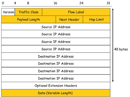
- The 40-byte IPv6 header shown above is larger than an IPv4 header, but contains far fewer fields that need to be interpreted by the routers involved in packet switching. This leads to an improvement in the performance of IPv6 packet switching devices, and less overall delay in delivering packets across a network.
- The important fields to note are:
- Source address: the 128-bit address assigned to the NIC of the host that created a packet.
- Destination address: the 128-bit address of the device to which the packet is sent. This field is used by routers when they make a packet forwarding decision.
- Data: this is the payload that an IP carries, typically a segment or datagram from the transport layer.
- Next header: this identifies the transport layer protocol encapsulated within a packet, using SAP 06 for TCP and 17 for UDP. Because IPv6 and IPv4 use the same SAPs to communicate with the transport layer, TCP and UDP are unaware which Internet layer protocol is in use. The next header field can also be used to identify optional extension headers.
- Hop limit: this performs the same function as the TTL field in the IPv4 header, but with a more descriptive name.
10 Network access layer – Ethernet
- Within Local Area Networks (LANs), Ethernet has become the most common network access technology. Ethernet is a family of related protocols standardised by the Institute of Electrical and Electronics Engineers (IEEE) in the IEEE 802.2 and 802.3 standards.
- Ethernet standards define the protocols and technology used within the network access layer. The network access layer accepts packets from the Internet layer and prepares them for transmission over a wide range of physical transmission media.
- Unlike the other layers of the TCP/IP protocol model, which are software based, network access is implemented in both hardware and software. When you install an Ethernet NIC, it provides appropriate hardware for physical connectivity and signalling for a particular type of transmission media, and provides software for framing and media access control services.
- Ethernet has evolved to support the demands of modern networks, and can operate over a wide range of speeds. Originally designed to operate at 10 Mbps over coaxial cable, it now supports both unshielded twisted pair (UTP) and fibre optic media, and commonly supported data rates within LANs are 100 Mbps, 1 Gbps and 10 Gbps, although it can support much greater speeds in specialised environments such as data centres.
- One function of Ethernet is to encapsulate Internet layer packets into PDUs called frames. The frame format remains consistent across all the popular Ethernet speeds, allowing older Ethernet systems to operate alongside newer variants:
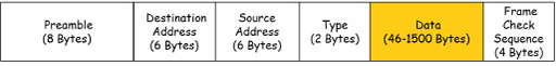
- The important fields to note are:
- Destination address: the 48-bit MAC address assigned to the NIC. Unlike IP, this address is assigned permanently to the NIC during manufacture.
- Source address: the 48-bit MAC address of the device to which the frame is sent.
- Type: the SAP identifying the Internet layer protocol packet encapsulated within the frame. A SAP of 0x800 is used for IPv4, and 0x86DD for IPv6.
- Data: the payload carried by the frame, typically a packet from either IPv4 or IPv6. The maximum size of a packet that a frame can carry is 1500 bytes.
- Frame check sequence (FCS): a mathematically generated code used to check that the frame has not been damaged during transmission – similar in function to the check-sum used by TCP. Unlike TCP, if Ethernet determines that a frame has been damaged, it drops it and relies on TCP to arrange for retransmission of the segment the frame contained.
- Network access protocols control when and how frames are transmitted over a particular transmission media, a technique referred to as media access control (MAC). The addresses used by Ethernet are named after this technique.
- Ethernet was originally designed to work on networks implemented as bus topologies, where all the devices were connected together using a single coaxial cable.
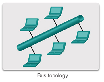
- The bus topology required the connected devices to take it in turn to send frames. This was because multiple frames travelling across the coaxial cable simultaneously would cause a collision, and this would prevent them being delivered to their destinations.
- To manage this process, Ethernet implements a media access control technique called carrier sense multiple access with collision detection (CSMA/CD). This forces devices to monitor the coaxial cable for the presence of frames (carrier sensing), and to wait until the cable is clear prior to transmitting their own. It also provides a mechanism for recovering from collisions in case the carrier sensing fails to prevent multiple frame transmission.
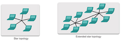
- Bus topology systems using coaxial cables have been superseded by star topology networks that use UTP cabling.
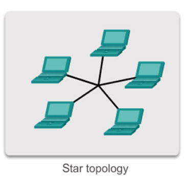
- Because UTP contains separate wires that support transmission and reception of frames, a star topology network connected by an Ethernet switch allows all devices to send and receive frames simultaneously without the risk of causing frame collisions. This means that CSMA/CD is not typically utilised in a modern network, although it is still available to provide compatibility with older systems.
- Ethernet is capable of connecting to coaxial, fibre optic and UTP transmission media, each of which requires a particular type of physical interface. The physical interface provides a suitable socket allowing the connection of a particular type of transmission media. It also contains hardware capable of converting the Ethernet frame into a signal suitable for transmission over the media. For example, Ethernet UTP connections use electrical signals for frame transmission, whereas fibre optic uses pulses of light.
- Ethernet NICs typically only support one type of physical interface, so it is important to select the correct card based on the transmission media in use.
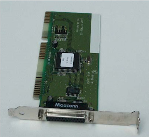
- Ethernet UTP NICs are the most common, and most cards can support a range of Ethernet speeds. For example, a 1 Gbps (Gigabit Ethernet) NIC will also be able to support 10 Mbps (Ethernet) and 100 Mbps (Fast Ethernet) operation. When you connect an NIC to an Ethernet switch, the two devices will negotiate the data rate and adopt the highest rate supported by both.
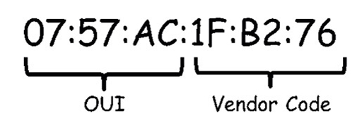
- Note that although the frame used by Ethernet is currently the same for most common varieties of the protocol, the actual physical signalling requirements are dependent on the data rates used. For example, 100 Mbps (Fast Ethernet) utilises four of the wires in a UTP cable, whereas 1 Gbps (Gigabit Ethernet) utilises all eight wires. Ethernet frames use a unique identifier called a MAC address to identify source and destination devices within an Ethernet network. An Ethernet MAC address is a 48-bit binary value, written as 12 hexadecimal digits, and every NIC card has a MAC address assigned to it during the manufacturing process.
- MAC addresses are globally unique. They are controlled by the IEEE, who allocate addresses to vendors. Vendors must register with the IEEE, who assign them unique a 24-bit (3-byte) code called an organizationally unique identifier (OUI).
- All MAC addresses assigned to an NIC or other Ethernet device must use that vendor’s assigned OUI as the first 3 bytes. The remaining 3 bytes are assigned a unique vendor code (serial number):
- Ethernet uses MAC addresses to manage the delivery of frames locally with a LAN, as opposed to IP addresses, which are used to provide end-to-end connectivity across multiple networks.
The role of MAC addresses in retrieving a webpage
- The diagram above shows the PC1 accessing a webpage from a WWW server, which you saw previously when you examined the role of transport layer ports. In this version the diagram shows the MAC addresses assigned to the Ethernet NICs of PC1 and the server.
- In the diagram, PC1 creates a segment containing the HTTP GET request, and selects appropriate source and destination ports. The segment is passed to IPv4, which encapsulates it within a packet containing the source IP address of PC1 and the destination IP address of the server.
- The packet is passed to the NIC, which encapsulates it within a frame containing the source MAC address of PC1’s NIC and the destination MAC address of the server NIC. The frame is converted to an appropriate signal for the transmission media and transmitted into the network.
- Network Ethernet switches use the destination MAC address within the frame to forward it towards the server. When the frame arrives at the server, it is accepted because the destination address it contains matches the MAC address of the server’s NIC.
- The server performs de-encapsulation to recover the packet and checks it to ensure that the destination IP address matches that assigned to the server. If it does, then the frame is again de-encapsulated and the segment is passed to the transport layer.
- Because MAC and IP addresses uniquely identify two devices, it is considered to be a unicast transmission. However, some network protocols need to communicate with all the devices in a local IP network simultaneously, which requires a broadcast transmission.
Broadcast transmission
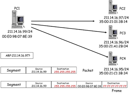
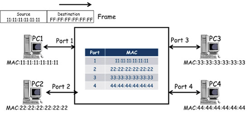
- The diagram above shows PC1 sending the same information to three different PCs in the same IP network. It is using the Address Resolution Protocol (ARP), which operates as a broadcast within an IP network. (Note that you will explore ARP further in the next course.)
- ARP creates a segment, which is encapsulated within a packet address, using the source IP address of PC1. However, the destination IP address is the ‘255.255.255.255’ address reserved by IPv4 for broadcasting to all devices within an IP subnet.
- The broadcast packet is encapsulated by the NIC into a frame, again using the source IP address of PC1. The destination MAC address is FF:FF:FF:FF:FF:FF, which is reserved by Ethernet for broadcasts to all devices within the local network.
- Network Ethernet switches forward the broadcast frame to all devices within the IP network, so client devices PC2, PC3 and PC4 all receive copies of the frame. Each device examines the frame, and although the broadcast destination address does not match the MAC address of their NIC, they de-encapsulate it and pass the packet to IPv4.
- IPv4 also accepts the packet because it recognises and accepts the broadcast IP address, and passes the segment to ARP.
Activity: ARP
Read the description of broadcast transmission in the box above. Can ARP use a broadcast to return information to PC1?
Answer
ARP could use a broadcast, but it will be able to identify PC1 using the source MAC address it finds in the frame carrying the ARP request, so it will use this instead.
11 Ethernet switch operation
- Modern Ethernet LANs are typically laid out in star and extended star topologies using Ethernet switches:
- Ethernet switches forward frames using the destination address within each frame it receives in order to make a switching decision. Ethernet switches automatically learn the MAC addresses of the device NICs connected to their ports, and store these in a MAC address table:
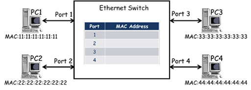
- The diagram above shows an Ethernet switch with four ports that is connected to four PCs. Each PC has an Ethernet NIC with a unique MAC address which, in the diagram, is simplified for clarity. (Although each PC is also assigned a unique IP address, they are not relevant to how the switch operates so are not shown.) The switch contains a MAC address table. In the diagram above it is empty as the PCs have not sent any frames.
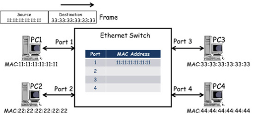
- PC1 transmits a frame towards PC3, including its own MAC address as the source and PC3’s MAC address as the destination. The frame is received by the port 1 of the switch, which examines the frame and records the source address against the port it was received at within the MAC address table. However, the switch makes its frame forwarding decisions based on destination addresses, and as it does not have an entry for 33:33:33:33:33:33, it is unable to select an exit port.
- Ethernet switches cannot drop frames if they cannot find an exit port, and so it forwards frames with unknown destinations out of all ports (flooding), in the hope that the frame will be delivered. In the example above, the frame is forwarded from ports 2, 3 and 4. Note that the switches do not send the frame out of port 1, as it has an entry in its MAC address table for MAC 11:11:11:11:11:11 and knows that this is the source of the frame.
- PC2 and PC4 ignore the frame as the destination MAC address it contains does not correspond to the MAC address of their NIC cards.
- The destination address of the frame matches the MAC address of PC3’s NIC, and the frame is accepted, de-encapsulated and processed by the relevant protocols. If a response is required, PC3 will generate a frame to carry the response back to PC1:
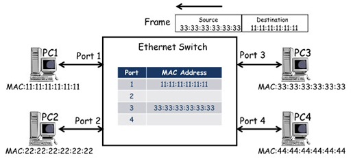
- The frame from PC3 arrives at port 3 of the switch, which records the source MAC address against the entry for port 3 in the MAC address table. The switch makes a switching decision based on the destination MAC address of the frame, which corresponds to the port 1 entry in the MAC address table. This time the switch knows where the destination MAC address is located, so it only forwards the frame to PC1.
- The switch will add MAC addresses to its table as frames arrive containing new source addresses, and if all the PCs are exchanging frames, the MAC table will quickly learn the MAC addresses of all connected PCs:
- This will ensure every received frame is delivered to the correct port, with the exception of frames that have a broadcast MAC destination address. The broadcast address cannot be associated with a port, so the switch behaves as it would for any destination address that doesn’t have an entry in the table – it floods the frame from all ports, except the one through which the frame was received.
- Ethernet switches learn MAC addresses in the same way as described above when connected via an extended star topology:
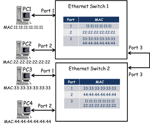
- In the diagram above the topology includes a second Ethernet switch, which is connected to the existing switch via port 3. Devices PC3 and PC4 have been moved to switch 2, and their MAC addresses have been added dynamically (or automatically) to the MAC address table against the new ports to which they are connected.
- Because switch 1 connects to switch 2 via port 3, the MAC addresses for PC3 and PC4 are listed against port 3 on switch 1 – this is the path switch 1 will use to forward frames destined for either of these PCs. Similarly, the MAC addresses of PC1 and PC2 are listed against port 3 on switch 2.
- Because switches dynamically add source MAC addresses to their MAC address tables, the switches have a mechanism for dynamically unlearning them. This prevents the table being filled with MAC address entries for devices that have been disconnected from the network. Thus most switches only maintain entries that are currently being used for frame forwarding. Once frame forwarding finishes, switches delete MAC address entries after a short delay of typically 5 minutes.
12 Router operation
- Because switches forward frames using frame MAC address information, they are unaware of the IP addresses within the packet they are carrying. Thus, if you need to connect together two or more IP networks, you need to use a router.
- Routers can access IP packets carried to them in frames, so they can make forwarding decisions based on the IP destination address they find. The forwarding of packets by routers is referred to as packet switching.
Packet switching
- Remember, when the host field of an IP address is all zeroes when read in binary, it identifies the particular IP network to which individual devices may be assigned:
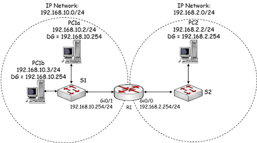
- PC1a has IP address 192.168.10.1/24, so it is within IP network 192.168.10.0/24.
- PC2 has IP address 192.168.2.2/24, so it is within IP network 192.168.2.0/24.
- Router R1 connects the two IP networks, allowing packets to be forwarded between them. The router needs to have interfaces that have IP addresses within the IP network to which it is directly connected:
- R1 Gigabit Ethernet 0/1 interface has IP address 192.168.10.254/24, so it is in the same IP network as PC1.
- R1 Gigabit Ethernet 0/0 interface has IP address 192.168.2.254/24, so it is in the same IP network as PC2.
- PC1a and PC2 use R1 as their default gateways (DG) to reach other IP networks. This means that each PC must know the IP address of the router interface that is within its IP network:
- PC1a uses R1 G0/1 as its default gateway.
- PC2 uses R1 G0/0 as its default gateway.
- Note that the PCs are connected to the router via Ethernet switches, so all the packets are transported across the network using Ethernet frames. However, the switches are not required to have IP addresses to do this.
- You may have noticed that PC1b is also connected to the same switch as PC1a, and is configured with an IP address and DG indicating it is in the same IP subnet. It does not need to go to R1 to exchange packets with PC1a because they are both in the same subnet – PC1a and PC1b can exchange packets in frames via the switch without using a default gateway.
- However, when PC1a and PC1b send packets to PC2, they will realise that the destination IP address is in another IP network, and will encapsulate their packets in frames that the switch will send towards R1 G0/1. You will investigate how this is achieved in more detail in the next module.
13 Routing table
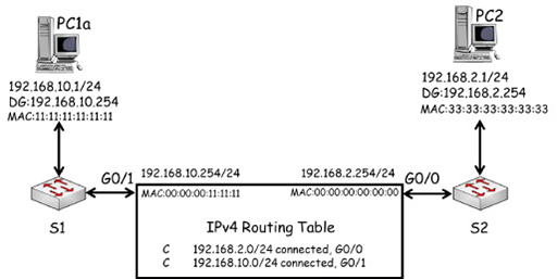
- Routers record all IP networks that they are aware of within an IP routing table. This is an important difference between switches and routers. A switch needs to learn which ports individual devices are connected to within the local network, whereas a router is only concerned with locating the IP networks connected to its interfaces.

- The entries in a routing table provide information about how a router learnt about each network, and which interface it should forward packets to that are destined for a particular network. In the diagram above, R1 learnt that network 192.168.10.0/24 exists because it was configured with an IP address (192.168.10.254/24) which falls within that network. Because this address was configured on G0/1, R1 will forward packets destined for network 192.168.10.0/24 towards that interface.
- You can see that the same is true for network 192.168.2.0/24, which is connected to R1 G0/0 interface. R1 thus considers these networks to be directly connected and it states this explicitly within each routing table entry.
- Packet forwarding by a router is similar to how an Ethernet switch forwards frames, but unlike in frame forwarding the router does not need to learn the IP addresses of individual devices.
Packet forwarding by a router
- Note that because the router is using Gigabit Ethernet interfaces, they are assigned MAC addresses. These are shown below the IP addresses of each interface and have been simplified for clarity. The IP, MAC and default gateway of PC1a and PC3 are also shown.
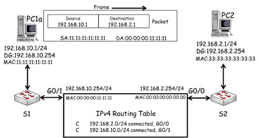
- In the diagram above, PC1a creates a packet destined for PC2. It uses its own IP (192.168.10.1) as the source, and PC2’s IP (192.168.2.1) as the destination. PC1 recognises that PC2 is on a different IP network, so it encapsulates the packet in a frame with the destination MAC address of its default gateway, R1 G0/1 (00:00:00:11:11:11).
- The packet is forwarded across the local network by S1 to R1 G0/1. R1 de-encapsulates the frame, and examines the packet’s destination IP address and compares it with the entries in its routing table. R1 has an entry for the IP network 192.168.2.0/24 which PC2 is within, which allows it to identify the exit interface for the network as G0/0.
- R1 switches the packet to interface G0/0, which encapsulates it within a frame using PC2’s MAC address as its destination:
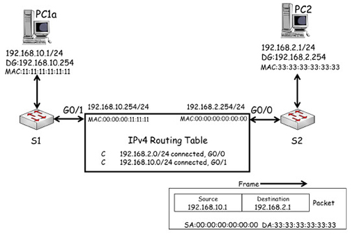
- The frame is forwarded to S2, which will deliver it to PC2 based on the destination MAC address it finds in the frame.
Activity: Source MAC address
In the previous example, the source address used in the frame identified R1 G0/0 as the source of the frame. Can you work out which source MAC address will be used when PC3 replies to PC1a?
Answer
PC3 will need to direct the frame to its default gateway using the MAC address of R1 G0/0 – 00:00:00:00:00:00.
- The example above illustrates the following points:
- The source and destination IP addresses are not changed when a packet is forwarded.
- A packet is encapsulated in two different frames during its transmission.
- The MAC addresses used within frames are all different.
- These points show that IP provides end-to-end delivery of packets across multiple IP networks using globally unique addresses. The source and destination addresses within a packet must remain the same to allow end devices to be identified.
- Ethernet frames are used for the delivery of data across local networks, using locally significant MAC addresses.
- There is one final difference in the way that routers and switches behave when they forward packets and frames (respectively).
- You saw previously that when a switch receives a frame which has a destination MAC address that is not currently in the MAC address table, the switch will flood the frame out of all ports, apart from the port that received the frame. Put simply, a switch cannot drop frames.
- However, a router will only forward a packet if it can find an entry in the routing table matching the destination IP address. If there is no matching entry, then the packet will be dropped.
14 Network address translation
- You have already come across NAT while learning about IP packet forwarding. Here you will learn about it in more detail to see how a router can provide NAT for multiple devices within the LAN.
- Home routers use a private IPv4 address range for devices within the home network. A private address cannot be routed over the Internet as it is used in millions of other networks across the world, and is therefore not unique.
- However, you will have a unique, public IP address assigned to your home router on the interface that connects to the Internet service provider. This is shown as 82.10.250.19 in the diagram below:
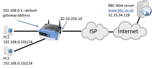
- The idea of NAT is to convert the source address from all outgoing LAN packets into the unique public address assigned to the home router, and vice versa for incoming packets from the Internet. You learnt about this previously in the context of a home network with only one PC. Here you will learn how NAT operates when there are multiple devices using a single public IP address as their source address.
- The image below shows packets transmitted from PC1 and PC2 towards a web server, which need to be routed towards the Internet by the home router:
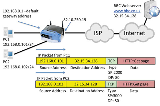
- Note that both packets have private IP source addresses, which cannot be routed towards the public IP address of the web server. The packet encapsulates a TCP segment, which uses port numbers to identify the application layer protocols carried in the segment.
- PC1 selects a random source port (2000), and a well-known destination port (DP) of 80, as it is communicating via HTTP with a web server.
- PC2 selects a random source port (3000), and a well-known destination port of 80, as it is also communicating via HTTP with the same web server.
- The packets are received by the home router, which performs NAT, converting the source addresses to its own Wide Area Network (WAN) interface public IP address (82.10.250.19). It also notes the source ports used in both packets and records them in its NAT table:
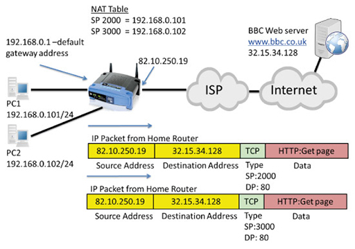
- The publicly addressed packets are forwarded through the Internet to the destination web server, which establishes two TCP connections with what it believes is the same device using two different source ports. It returns the requested webpage in a series of packets to the two different TCP destination ports:
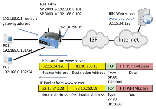
- The returned IP packets are addressed with the web server as the source and the public address of the home router WAN interface as the destination. The TCP port numbers have also been reversed, with port 80 indicating the segment is from a web server, and port 2000 and 3000 identifying the ports used by PC1 and PC2 respectively.
- The home router accepts the incoming packets. It examines the destination ports and tries to match them with the source ports it has recorded in its NAT table in order to replace the public source address with the correct, private IP address for PC1 or PC2:
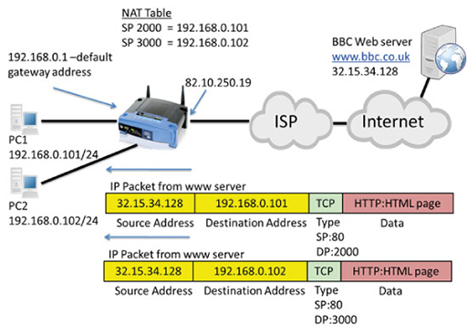
- Because NAT mapped source port 2000 to IP address 192.168.0.101, the packet with destination port 2000 will have its destination IP address changed to 192.168.0.101 and will be forwarded to PC1.
- Because NAT mapped source port 3000 to IP address 192.168.0.102, the packet with destination port 3000 will have its destination address changed to 192.168.0.102, and will be forwarded to PC2.
- Using port numbers within the home router NAT process is essential, as it allows translation to occur for multiple devices.
15 Activities
Activity: Error detection
TCP/IP protocols use check-sums to detect errors in the data they are responsible for transmitting. But how do errors occur and can we do anything about them?
Errors can creep into to an electrical signal at many points in a communication. They are caused by electrical interference and create electrical noise on the line, which can corrupt data. A digital ‘1’ may become a ‘0’, or a ‘0’ may become a ‘1’.
We have several techniques for detecting when an error occurred, and some techniques can say where the error occurred in the data. If we know where it occurred, we can simply ‘flip’ the bit back over.
Play CS Unplugged’s activity to learn more about one such technique.
Activity: Frame check sequence
Activity: Protocol stacks (Packet Tracer)
Complete the activities in the Black Lab Book to put into practice what you have learned in this course about the complex interaction between the TCP/IP suite protocols.
You will need:
16 Resources
TCP/IP
For more information, take a look at the following resources.
- Read The Geek Stuff’s page about TCP/ IP fundamentals.
- Watch the following video about theTCP/IP Model of Networking:
Understanding the persistence of data on the Internet
- Watch this video about digital footprints:
- The following video explores the risks of posting photos online.
- The video below explores how you can lose control of content you post online.
- In the video that follows you can learn about the risks of web cams.
- Watch this video to learn more about the dangers surrounding strangers you meet online.
17 End of course quiz
Now it’s time to test what you’ve learned in a quiz.
18 Acknowledgements
Grateful acknowledgement is made to the following sources:
Figure 1: Birmingham City University (BCU)
Figure 2: Birmingham City University (BCU)
Figure 3: Birmingham City University (BCU)
Figure 4: Birmingham City University (BCU)
Figure 5: Birmingham City University (BCU)
Figure 6: Birmingham City University (BCU)
Figure 7: Birmingham City University (BCU)
Figure 8: Birmingham City University (BCU)
Figure 9: Birmingham City University (BCU)
Figure 10: Birmingham City University (BCU)
Figure 11: Birmingham City University (BCU)
Figure 12: Birmingham City University (BCU)
Figure 13: Birmingham City University (BCU)
Figure 14: Cisco
Figure 15: Cisco
Figure 16: Jonas Bjork This file is licensed under the Creative Commons Attribution-Share Alike Licence http://creativecommons.org/ licenses/ by-sa/ 2.0/
Figure 17: Birmingham City University (BCU)
Figure 18: Birmingham City University (BCU)
Figure 19: Birmingham City University (BCU)
Figure 20: Cisco
Figure 21: Birmingham City University (BCU)
Figure 22: Birmingham City University (BCU)
Figure 23: Birmingham City University (BCU)
Figure 24: Birmingham City University (BCU)
Figure 25: Birmingham City University (BCU)
Figure 26: Cisco NetAcad/Birmingham City University (BCU)
Figure 27: Birmingham City University (BCU)
Figure 28: Birmingham City University (BCU)
Figure 29: Birmingham City University (BCU)
Figure 30: Birmingham City University (BCU)
Figure 31: Birmingham City University (BCU)
Figure 32: Birmingham City University (BCU)
Figure 33: Birmingham City University (BCU)
Figure 34: Birmingham City University (BCU)
Figure 35: Birmingham City University (BCU)
Every effort has been made to contact copyright holders. If any have been inadvertently overlooked the publishers will be pleased to make the necessary arrangements at the first opportunity.