Use 'Print preview' to check the number of pages and printer settings.
Print functionality varies between browsers.
Printable page generated Thursday, 23 July 2026, 6:04 PM
The operation of LAN and WAN hardware and protocols
1 Introduction to Wide Area Networks
- At home, your Local Area Network (LAN) might connect together devices over a distance measured in tens of metres. At work or school, the LAN might connect devices over hundreds of metres. A Wide Area Network (WAN) operates over a much larger area, as they interconnect LANs to allow them to exchange data.
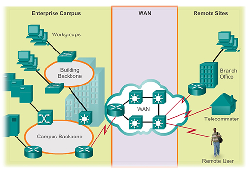
- For example, in the diagram above a large business network needs to provide a connection to a remote branch office, and to employees who work from home (telecommuters) and who are travelling (remote users). This connection is provided by a WAN. WANs are operated by a service provider, and businesses pay them a fee in order to gain access.
- WAN service providers are businesses that provide WAN services using a variety of technologies, including the telephone network, cable and satellite. The WAN allows employees to connect to the business network in order to carry out work related tasks – the connection is not primarily for accessing the Internet.
- Why doesn’t the company set up its own WAN to save money? Traditionally, due to the distance that WANs operate over, setting one up would cost a substantial amount of money as the business would need to purchase the necessary cabling, fibre and satellite systems. Setting up a WAN would therefore prove to be extremely expensive and time-consuming, so most businesses prefer to rent WAN services from an established service provider.
- Consider your home network, which probably provides you with access to the Internet. You too are paying for WAN services as your Internet Service Provider (ISP) is a business that specialises in connecting households to the Internet. They have invested a considerable amount of money in creating a suitable WAN infrastructure that allows thousands of domestic users (who pay a fee) to connect.
Activity
Do you know who your ISP is? How much do they charge for Internet access?
- Domestic networks are primarily connected to an ISP for Internet access, unlike business WANs. Because there are a great many different reasons for creating a WAN, there are many different types of WAN technology available. Most commonly a business WAN needs to support its employees and remote offices, and it will have a different set of requirements to a home user requiring just Internet access. Traditionally, businesses and home users have used different types of WAN technology to provide connectivity.
- As the need to access the Internet has become more widespread, broadband technology has been introduced to provide connections for home, school and small business users. This technology utilises a wide band of frequencies, transmitted over a single transmission media (coaxial, UTP, fibre, wireless), to provide an Internet service that is always on and has a high data rate.
- Broadband provides the connection between a home, school or small business and the ISP. Once within the ISP, different WAN technology will be used to transfer the data around the ISP network and between other ISPs.
- However, it is becoming increasingly common for even large businesses to connect to the Internet to provide connection between their LANs, as opposed to using more traditional WAN solutions. Thus, many businesses are also using broadband connectivity to provide WAN connectivity.
- There are four main types of broadband WAN connectivity available via UK ISPs:
- Digital Subscriber Line (DSL)
- cable
- fibre optic
- wireless.
2 Digital Subscriber Line
- DSL technology is an always-on connection technology that uses existing twisted-pair telephone lines to transport high bandwidth data and provide IP services to subscribers.
- Multiple DSL subscriber lines are multiplexed into a single, high-capacity link using a DSL access multiplexer (DSLAM) which is installed in the local telephone exchange by the service provider. The digital multiplexed output can then be transported through the service provider’s network by whichever WAN technology they have chosen to implement.
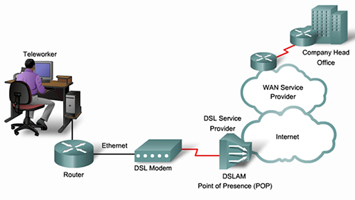
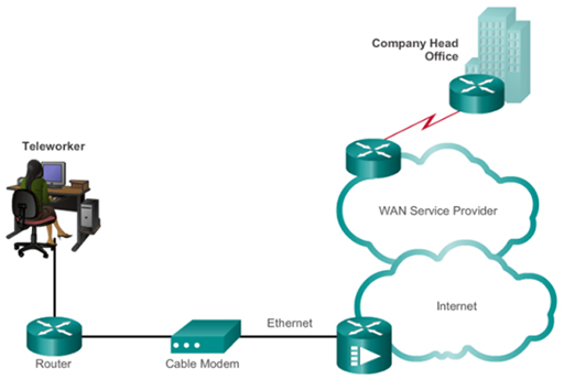
- The diagram above shows a home office worker connecting to their ISP using DSL. This provides them with a connection to the Internet and to the business WAN of their employer.
- DSL provides high-speed connections over the copper wires installed for the domestic public switched telephone network (PSTN) or ‘plain old telephone service’ (POTS). The existing phone system only uses frequencies between 0 and 4 KHz, but DSL can use the additional bandwidth available between 4 KHz and 1 MHz for high-speed data services.
- DSL divides the 4 KHz to 1 MHz bandwidth into different transmit (upstream) and receive (downstream) channels, which it uses to connect the home to the ISP. The diagram below shows a DSL system with more downstream channels than upstream channels, meaning that it can support higher download than upload speeds. This is referred to as asynchronous DSL (ADSL), and is ideal for home users connecting to the Internet, as the majority download rather than upload content.
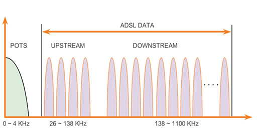
- Another form of DSL provides equal upload and download speeds, and is referred to as symmetric DSL (SDSL). SDSL is popular with businesses which chose to create WAN connections between their sites using the Internet as opposed to more traditional WAN solutions.
- There are many varieties of DSL, including some that support data rates exceeding 100 Mbps. Regardless of the variety used, the data rates are dependent on the actual length of the physical cabling between the user and the local telephone exchange. For satisfactory ADSL service, the cabling must be less than 5.5 km.
- ISPs provide home users with a router capable of connecting to a telephone system line socket. The home router will use an internal modem to create the required upstream and downstream channels, allowing its WAN port to communicate with the DSLAM at the local telephone exchange over the phone line (local loop):
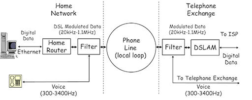
- There is a gap called a guard band between the telephone voice signal and the modulated DSL signal, which is intended to prevent interference. However, most DSL connections still utilise a filter, connected into the telephone socket, to prevent the DSL signal being picked up by the telephone.
- A filter is also used at the exchange to separate the telephone signal, which is fed to the telephone exchange, and the DSL signal, which is sent to the DSLAM and then towards the ISP WAN for connection to the Internet.
- In the UK, all ISPs must be able to install their DSLAM equipment within a local exchange, allowing them to offer their services to domestic customers connected via the copper cabling installed and owned by BT/Openreach.
3 Cable
- Cable television systems were introduced in the USA in the late 1940s as a means of distributing television programs received by a single antenna to users in remote areas with poor reception. Cable systems have now grown in popularity as a means of distributing a wide number of television channels to users within cities without the need for individual homes to have external antenna systems.

- Modern cable systems can provide two-way communication between homes and the cable system operators, and now offer advanced telecommunications services, such as a telephone service and high-speed Internet access, alongside the usual digital cable television.
- Cable system providers traditionally used coaxial cable to connect devices throughout their network. Because of the increase in demand for bandwidth by the service now available to home users, most cable providers use fibre optic cabling within the trunks used to connect together their network and only utilise coaxial cable to provide the link from their local junction box (normally a green, steel street cabinet) to the household. This is called a hybrid fibre-coaxial (HFC) system.
- Home users are normally provided with a cable modem which connects to the coaxial cable used to deliver the television, telephone and Internet services. The cable modem provides suitable output for the devices required – TV to the television, voice services to the telephone, and data to the home router.
- Typical cable modems use Ethernet to provide the connection to the home router WAN port. Thus, home routers designed for DSL and cable systems are not compatible, as their WAN ports are designed to support different signals.
- Although cable providers generally offer a higher speed Internet service than DSL, the speed depends on the number of local customers, and as the number of users increases, the data rate decreases. Cable customers must use the ISP services of the cable provider as cable operators are not required to open up their network to competitors.
4 Fibre optic
- Fibre optic transmission media consists of a glass core surrounded by a slightly less optically dense cladding material. Pulses of light, representing binary digits, are transmitted into the fibre using laser or LEDs and propagate along its length due to refraction at the core/cladding interface.
- Fibre optic provides extremely high data rates over great distances, and fibre optic cables are used to provide telecommunication links between continents using cables laid across the seabed. Because many WAN connections need high data rate links between service providers based in different countries, fibre optics are commonly used.
- As service providers need to use a common, standardised interface to exchange data, their fibre networks use either Synchronous Optical Networking (SONET) or Synchronous Digital Hierarchy (SDH) standards. These standards define how data is transferred over high data rate circuits stretching over thousands of kilometres.
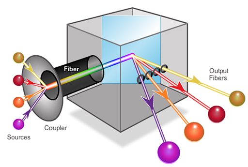
- A newer fibre optic technique used for long distance communications is dense wavelength division multiplexing (DWDM), shown above. This allows a single fibre to support multiple channels (around 80, only 4 shown) by using different wavelengths (i.e colours) of light, with each channel supporting a data rate of 10 Gbps.
- DWDM fibre optic technology is now used in all the submarine cables laid between the continents.
- Some home users are also able to benefit from the high data rates available from fibre optic through a number of changes to the existing network. For example, fibre to the home (FTTH) is replacing the copper cabling that used to provide the ‘local loop’ connection between households and service providers, and offers data rates of approximately 1 Gbps. Another upgrade involves the use of fibre to the cabinet (FTTC), where fibre optic is run from the service provider to the local street cabinet, which is then connected to individual properties using copper cabling.
- Because FTTC still utilises copper, the data rate decreases as the distance between the cabinet and the household increases. By around 1500 m the data rate will have dropped to 15 Mbps in a fibre/DSL system. Cable FTTC uses coaxial cable to the home, which supports higher data rates of between 50–150 Mbps.
- Although both cable and DSL operators have started to offer FTTH/FTTC, it is expensive and time-consuming to roll out, so availability is currently limited.
5 Wireless
- The use of radio frequencies to support broadband access for home and small business users has been limited by the low transmission range typically associated with the available wireless technology. However, new developments in broadband wireless technology are available that provide improved connectivity:
- municipal WiFi
- Worldwide Interoperability for Microwave Access (WiMAX)
- cellular.
6 Municipal WiFi
- Many cities (such as London) have begun setting up municipal WiFi networks utilising the same range technology that is used within homes. Most of these networks are provided to allow the emergency services to access data services when attending an incident, but often allow residents to access the network for Internet connectivity too.
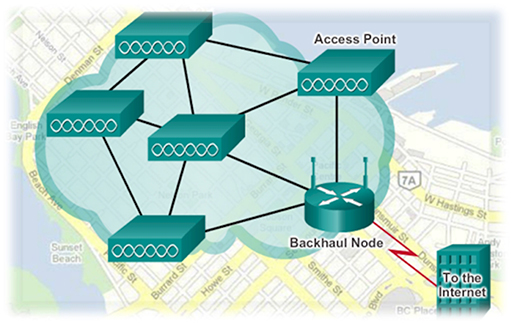
- Most municipal wireless networks utilise a mesh topology, as shown in the figure above. In this topology the access points are all interconnected wirelessly and several access points provide coverage for the same area. The use of a wireless mesh reduces the amount of cabling required to implement it and the overlapping coverage is able to maintain service even if several access points fail.
- Note that the access points connect to a wired router (backhaul node), which provides connectivity to a service provider for Internet access.
- Because subscribers to municipal WiFi are connecting to access points that may be located quite a distance from their home, they require WiFi modems with improved receivers and directional antenna to optimise the weak signal that they receive.
- Some UK based ISPs offer a form of municipal WiFi by allowing their customers to access the Internet by connecting to other subscriber’s home routers via WiFi wherever they happen to be in the UK.
7 Worldwide Interoperability for Microwave Access
- WiMAX operates in a similar manner to WiFi, but provides a higher data rate over a much wider coverage area to more customers.
- The WiMAX standard (802.16) provides data rates up to 70 Mbps, and operates over a range of frequency bands from 2 to 6 GHz.
- WiMAX uses a network of towers, similar to those used for cellular telephones, which provide a broadband connection to customers within 50km. The towers themselves provide point-to-point wireless connectivity to the service provider’s premises, where it is routed to the Internet. WiMAX is thus able to provide coverage to rural areas beyond the range of DSL and cable broadband services.
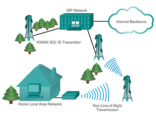
- WiMAX, as shown above, can provide both point-to-point links between towers and full mobile cellular type access to subscribers, and is likely to supersede municipal WiFi as the preferred wireless broadband technology. WiMAX customers connect to the service using a variety of WiMAX capable devices, such as home routers, or mobile devices with integrated WiMAX technology.
8 Cellular wireless
- Cellular or mobile telephony provides telephone services using wireless technology, allowing users to place calls from a wide range of handsets (smart phones, laptops, tablets) to a network of fixed base stations (or cell towers). The base stations are connected to the cellular service provider’s network either by point-to-point or wired links, allowing calls to be placed to other cellular users and telephones within the PSTN.
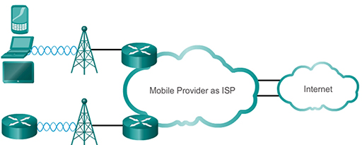
- Cellular providers also support connectivity for data services such as email and web surfing, and cellular wireless has become an increasingly popular way of accessing Internet based services for mobile users. Because of the comprehensive cellular coverage of all but the most remote areas of the UK, it can also be used to provide Internet WAN services for domestic subscribers using cellular-capable home routers.
- The data rate, wireless frequencies and coverage areas available via cellular WANs depend on the technology utilised. This is referred to as ‘generations’, with each passing generation providing an improved service when compared to its successor.
- Common cellular industry terms include:
- 3G wireless, or third generation cellular access, is a range of technologies supporting wireless Internet access. 3G systems can support data rates of between 7.2 and 42 Mbps, depending on the actual technology.
- 4G/Long Term Evolution (LTE), or fourth generation cellular access, can support a theoretical maximum data rate of 150 Mbps.
- The data rate actually achieved via cellular WAN is extremely variable as there are many factors that can significantly reduce the rate from the theoretical maximum, such as distance from the cell tower, movement and electromagnetic interference.
9 Sending data across the LAN
- Your home network provides access to both the devices you have installed within your house, and to the Internet via the WAN connection provided by your ISP. Before considering how data is sent to and from the WAN, we will examine how devices within the home network exchange data.
- Consider the home network shown below, where PC1 is sending a file to a printer connected to the network:
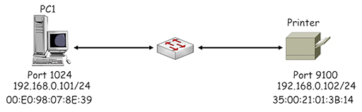
- Both PC1 and the printer are using IP addresses within the private range of addresses in IP network 19.168.0.0/24. The printer is listening on a registered port of 9100 and the PC has selected registered port 1024 to identify its TCP session with the printer. Both devices are fitted with an Ethernet NIC card, which have manufacturer assigned MAC addresses.
- PC1 first performs a check on the planned source and destination addresses to see which IP networks they are within:
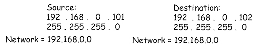
- PC1 uses its own subnet mask (/24 – 255.255.255.0) to determine the IP network that it is within. The mask identifies the first three octets of the IP address as belonging to the IP network address: 192.168.0. It then simply adds a ‘0’ to the end to complete the address: 192.168.0.0. PC1 then uses the same subnet mask to see which IP network the destination address is within and achieves the same result, 192.168.0.0.
- PC1 recognises that the source and destination IP addresses are within the same IP network, so there is no requirement to forward them to a default gateway (the home router) for delivery to a different IP network.
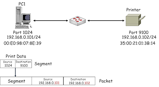
- PC1 encapsulates the print information into a succession of TCP segments, which are then encapsulated in appropriately addressed IP packets. The source address identifies PC1 (192.168.0.101) and the destination address identifies the printer (192.168.0.102):
- The packet needs to be encapsulated within an Ethernet frame by the NIC on PC1. This appears to be straightforward until you consider the destination MAC address field. How does PC1 learn the MAC address burnt into another device’s NIC?
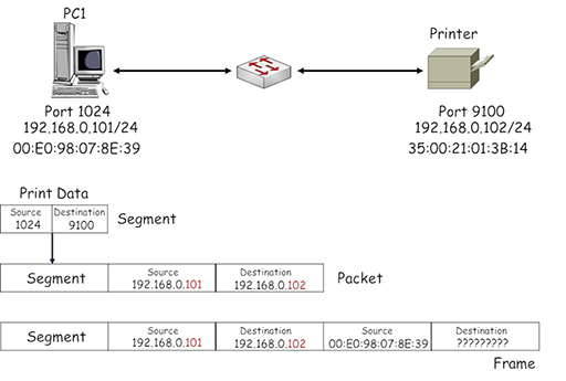
- At this point, PC1 is unable to identify the correct MAC address to place in the destination field of the frame, so the frame cannot be transmitted to the printer. Consequently PC1 initiates a broadcast communication to all the devices in its IP subnet using the Address Resolution Protocol (ARP), requesting information about the MAC address associated with the device using IP address 192.168.0.102:
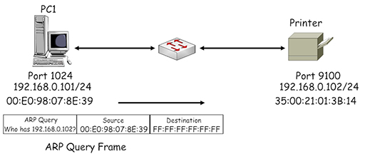
- Note the destination address used by the ARP is FF:FF:FF:FF:FF:FF – this is a broadcast address, which is flooded by the Ethernet switch from all its ports (apart from the one the address was received on). Thus, all the devices within the LAN receive the ARP query, but only the printer responds as the query contains its IP address. It returns an ARP response, identifying its assigned MAC address:
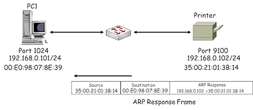
- PC1 uses the MAC address received in the ARP response to complete the destination MAC address field in the frame it is using to send data to the printer:
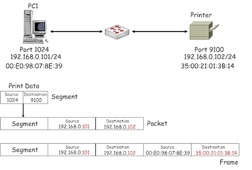
- Because ARP uses a broadcast destination address it can have a large impact on the operation of Ethernet switches, which are required to flood multiple copies of it from all their ports. To ease this burden, PC1 creates a local table called an ARP cache in which it stores all the IP address/MAC address pairings it has learnt. As a result, subsequent frames created by PC1 addressed to the printer will use the ARP cache to find the required destination address instead of using ARP.
- The entries in the ARP cache have a lifetime associated with them, which is constantly updated while the device is sending frames using the entries. Once the device stops sending frames the entries will timeout and be removed from the cache. This prevents the cache becoming full of outdated MAC address information.
10 Sending data to the WAN
- When your home devices forward data towards the Internet, they use source and destination IP addresses that sit within different IP networks, so the data must be forwarded via the default gateway (home router). Consider the network shown below, where PC1 wishes to access the WWW server:
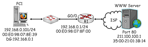
- PC1 performs a check on the planned source and destination addresses to see which IP networks they are within by comparing them with its own subnet mask:

- PC1 recognises that the destination address is on a different IP network and that it must send packets via the default gateway it has been configured to use: 192.168.0.1. PC1 encapsulates the webpage request into a succession of TCP segments, which are then encapsulated in appropriately addressed IP packets. The source address identifies PC1 (192.168.0.101) and the destination address identifies the web server (211.100.100.1):

- Why doesn’t PC1 use the address of the default gateway (192.168.0.1) as the destination of the packet? Remember that IP addresses are used to provide end-to-end connectivity between devices located on different IP networks – they are not used to identify any intermediate devices through which the packet is forwarded. PC1 therefore encapsulates the packet within an Ethernet frame and uses its destination MAC address to deliver the frame to the default gateway.
- Once again, PC1 uses ARP to determine the MAC address being used by the interface with IP address 192.168.0.1:
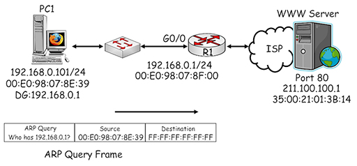
- The ARP query generated by PC1 is sent in a broadcast frame and delivered to all the devices in the home LAN. R1 recognises its own IP address within the ARP query and returns an ARP response providing its MAC address:

- PC1 uses the MAC address it received in the ARP response to complete the destination MAC address field in the frame it is using to send data to the default gateway:

- The frame is delivered across the local network to the gigabit interface of the home router, R1. Because the destination MAC address of the frame matches the MAC assigned to the interface, the router accepts the frame and de-encapsulates it to recover the packet. The router then tries to match the destination IP address with an entry within its own routing table so it can make a forwarding decision:

- The image above shows the home router in slightly more detail, including the routing table which contains two entries. The devices within the home network are connected to the router via the G0/0 interface, so network 192.168.0.0/24 appears directly connected. The second entry shows a default route, connected to the external WAN interface G0/1. It may look strange as it consists of an all zero IP address and subnet mask. However, this means that it will match all possible destination IP addresses and forward them from interface G0/1 towards the ISP.
- Why is a default route required? Remember, a router will only forward a packet if it finds a match for its destination IP address within the local routing table. If the home router did not use a default route it would need to have an entry for every possible destination network within the Internet, and it simply does not have enough memory to do that.
- By using the default route to forward all packets to the ISP, home users are relying upon the routers within the service provider’s network having sufficient routing information to be able to deliver their packets to the required destination networks.
- Once the router has determined that the packet needs to be forwarded from G0/1, it has three tasks:
- switch the packet to interface G0/1
- perform Network Address Translation (NAT) on the source address of the packet
- encapsulate the packet in an appropriately addressed frame.
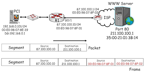
- The diagram above shows more detail about the connection between the home router and the ISP. The G0/1 interface is connected via whichever broadband technology is being used (DSL, cable or wireless) to a router within the ISP, which is configured with IP and MAC addresses.
- Referring to the diagram, note that the source IP address of the packet has been converted by NAT to 87.100.100.10, which is the public IP address that uniquely identifies the home router within the Internet.
- The packet is then encapsulated within an Ethernet frame, which uses the MAC address of home router interface G0/1 as its source and the MAC address of the ISP router interface as its destination.
- Subsequent routers that forward the packet towards the WWW server will not change the source IP address, otherwise reply packets would not be able to locate the home router.
- The packet will be encapsulated in a new frame every time it is forwarded by a router. The frames that are used may not be Ethernet – it depends on the type of WAN technology that is utilised by the devices which forward the packet to its destination.
- Another function provided by routers is to limit the spread of broadcast traffic such as ARP. Imagine what would happen if ARP could be propagated across the Internet – every time an ARP was generated, on any device, it would be sent to every other device in the world. This is obviously extremely undesirable and router interfaces create a broadcast domain – they will examine broadcast traffic, but they will not forward it onto other networks.
11 Point-to-Point Protocol over Ethernet
- So far, you have looked at the network access layer protocol Ethernet and its role in transporting frames between devices within networks. It is also important to note that a wide variety of other network access protocols are utilised within service provider networks, some of which include:
- High-Level Data Link Control (HDLC)
- Point-to-Point Protocol (PPP)
- Asynchronous Transfer Mode (ATM)
- You will not encounter these protocols within a home network, but some of the functions of PPP are utilised to support the connection between a home router and a service provider.
- PPP functions include the ability to assign addresses to remote devices (in a similar manner to DHCP) and to authenticate devices attempting to connect to a network. Authentication is the process in which a user provides information, such as a username and password, to identify themselves to the service provider. Authentication is obviously very important from a service provider’s point of view, as it allows them to restrict access to their network to genuine (paying) subscribers.
- Many ISPs use Ethernet framing to connect households and their own networks, but Ethernet on its own cannot support authentication. This leads to the development of Point-to-Point Protocol over Ethernet (PPPoE), which is a network access protocol capable of encapsulating PPP frames within Ethernet frames:
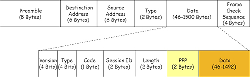
- Because the PPP frame is included within the data payload area, it reduces the room available for carrying packets. PPPoE allows ISPs providing ADSL broadband to use the functions of PPP, particularly authentication, while still providing an Ethernet service.
- Another option for connecting a home router to an ISP is PPP over ATM (PPPoA), which provides essentially the same function as PPPoE for service providers who have implemented ATM routing within their WAN.
- The main difference between the two protocols from a home user’s point of view rests in authentication. PPPoA requires the home router to be configured with a username and password in order for it to connect to the ISP. Any home device that connects to the home router is then able to access the Internet via the ISP. PPPoE offers the same service but, additionally, it can be installed as a client application on individual devices, allowing them to establish separate, authenticated sessions with the ISP.
12 Activity
Activity: Understand the devices and protocols used in LAN and WAN networks (Packet Tracer)
This module has explored the interaction between devices located on the LAN as they access WAN services in theory. Try this activity to see the interaction in action.
You will need:
13 End of course quiz
Now it’s time to test what you’ve learned in a quiz.
14 Acknowledgements
Grateful acknowledgement is made to the following sources:
Figure 1: Cisco
Figure 2: Cisco
Figure 3: Cisco
Figure 4: Birmingham City University (BCU)
Figure 5: Cisco
Figure 6: Cisco
Figure 7: Cisco
Figure 8: Cisco
Figure 9: Cisco
Figure 10: Cisco
Figure 11: Birmingham City University (BCU)
Figure 12: Birmingham City University (BCU)
Figure 13: Birmingham City University (BCU)
Figure 14: Birmingham City University (BCU)
Figure 15: Birmingham City University (BCU)
Figure 16: Birmingham City University (BCU)
Figure 17: Birmingham City University (BCU)
Figure 18: Birmingham City University (BCU)
Figure 19: Birmingham City University (BCU)
Figure 20: Birmingham City University (BCU)
Figure 21: Birmingham City University (BCU)
Figure 22: Birmingham City University (BCU)
Figure 23: Birmingham City University (BCU)
Figure 24: Birmingham City University (BCU)
Figure 25: Birmingham City University (BCU)
Figure 26: Birmingham City University (BCU)
Every effort has been made to contact copyright holders. If any have been inadvertently overlooked the publishers will be pleased to make the necessary arrangements at the first opportunity.