11 Ethernet switch operation
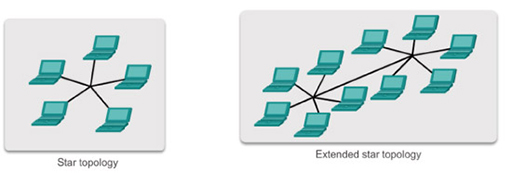
- Modern Ethernet LANs are typically laid out in star and extended star topologies using Ethernet switches:
- Ethernet switches forward frames using the destination address within each frame it receives in order to make a switching decision. Ethernet switches automatically learn the MAC addresses of the device NICs connected to their ports, and store these in a MAC address table:
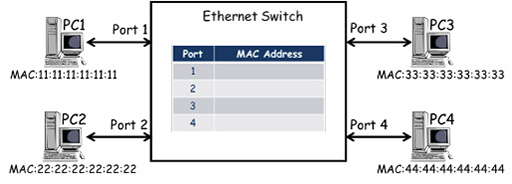
Figure 21
- The diagram above shows an Ethernet switch with four ports that is connected to four PCs. Each PC has an Ethernet NIC with a unique MAC address which, in the diagram, is simplified for clarity. (Although each PC is also assigned a unique IP address, they are not relevant to how the switch operates so are not shown.) The switch contains a MAC address table. In the diagram above it is empty as the PCs have not sent any frames.
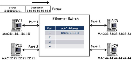
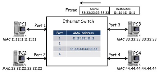
- PC1 transmits a frame towards PC3, including its own MAC address as the source and PC3’s MAC address as the destination. The frame is received by the port 1 of the switch, which examines the frame and records the source address against the port it was received at within the MAC address table. However, the switch makes its frame forwarding decisions based on destination addresses, and as it does not have an entry for 33:33:33:33:33:33, it is unable to select an exit port.
- Ethernet switches cannot drop frames if they cannot find an exit port, and so it forwards frames with unknown destinations out of all ports (flooding), in the hope that the frame will be delivered. In the example above, the frame is forwarded from ports 2, 3 and 4. Note that the switches do not send the frame out of port 1, as it has an entry in its MAC address table for MAC 11:11:11:11:11:11 and knows that this is the source of the frame.
- PC2 and PC4 ignore the frame as the destination MAC address it contains does not correspond to the MAC address of their NIC cards.
- The destination address of the frame matches the MAC address of PC3’s NIC, and the frame is accepted, de-encapsulated and processed by the relevant protocols. If a response is required, PC3 will generate a frame to carry the response back to PC1:
- The frame from PC3 arrives at port 3 of the switch, which records the source MAC address against the entry for port 3 in the MAC address table. The switch makes a switching decision based on the destination MAC address of the frame, which corresponds to the port 1 entry in the MAC address table. This time the switch knows where the destination MAC address is located, so it only forwards the frame to PC1.
- The switch will add MAC addresses to its table as frames arrive containing new source addresses, and if all the PCs are exchanging frames, the MAC table will quickly learn the MAC addresses of all connected PCs:
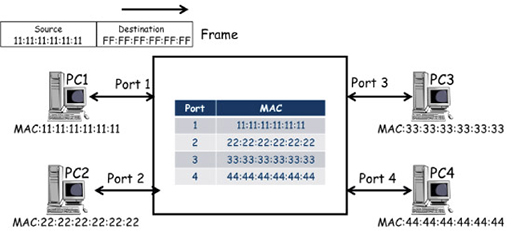
- This will ensure every received frame is delivered to the correct port, with the exception of frames that have a broadcast MAC destination address. The broadcast address cannot be associated with a port, so the switch behaves as it would for any destination address that doesn’t have an entry in the table – it floods the frame from all ports, except the one through which the frame was received.
- Ethernet switches learn MAC addresses in the same way as described above when connected via an extended star topology:
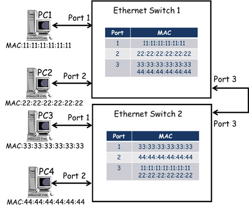
Figure 25
- In the diagram above the topology includes a second Ethernet switch, which is connected to the existing switch via port 3. Devices PC3 and PC4 have been moved to switch 2, and their MAC addresses have been added dynamically (or automatically) to the MAC address table against the new ports to which they are connected.
- Because switch 1 connects to switch 2 via port 3, the MAC addresses for PC3 and PC4 are listed against port 3 on switch 1 – this is the path switch 1 will use to forward frames destined for either of these PCs. Similarly, the MAC addresses of PC1 and PC2 are listed against port 3 on switch 2.
- Because switches dynamically add source MAC addresses to their MAC address tables, the switches have a mechanism for dynamically unlearning them. This prevents the table being filled with MAC address entries for devices that have been disconnected from the network. Thus most switches only maintain entries that are currently being used for frame forwarding. Once frame forwarding finishes, switches delete MAC address entries after a short delay of typically 5 minutes.
Back to previous pagePrevious
10 Network access layer – Ethernet