
Background (Exploring resistance in electrical circuits)
Background
Resistors are found in most electrical circuits and their role is to resist the flow of electrical current. Like the wires found in an electrical circuit, resistors are able to conduct current, but they do so less effectively. The resistors shown in Figure 1 are made from a mixture of powdered carbon, which is a conductor of electricity, and non-conducting powder. It is the amount of carbon that determines how well a resistor can conduct electricity and therefore the value of its resistance.
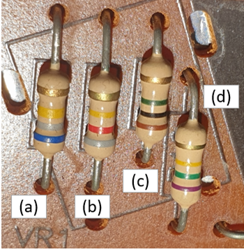
Figure 1. Four resistors in a circuit board (labelled (a) to (d)) of a smoke alarm (note that each has a different colour coding in the form of four colour bands – you will learn more about this coding system later in this lesson).
|
Activity 1: Resistors |
|
Note down the colour bands for each of the resistors (a) to (d), for example, (a) has blue/grey/yellow bands that are close together and a gold band set apart. You will use this information to identify the resistance values for each of these resistors later in this lesson. |
Figure 2 is a representation of a simple electrical circuit consisting of a single resistor and a battery. There is also a voltmeter to measure the voltage across the resistor and an ammeter to measure the current flowing in the circuit (you will notice that the ammeter is ‘in line’ and forms part of the circuit whereas the voltmeter is external to the circuit).
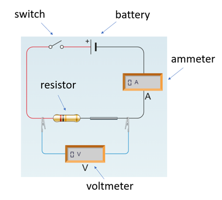
Figure 2. A simple electrical circuit with a single resistor.
The resistance of an electrical circuit is calculated as the number of volts (V) of battery power needed to allow a current of 1 ampere (A) to flow around the circuit. A low resistance circuit might need only 2 volts per ampere such that a 1 V battery would produce a current of 0.5 A.
The unit of resistance is therefore V per A – however, today we call this unit an ohm (Ω) after George Ohm, a 19th century physicist who was an early investigator of how current flows in electrical circuits.
ohm = volts/ampere
The current (I) flowing in an electrical circuit is defined by Ohm’s law where the unit for current (I) is A, the unit for voltage is V and resistance (R) is Ω:
I = V/R
Ohm’s law can be rearranged so that if you know two of the values it is possible to calculate the third. So, if you know the voltage across a resistor and the current flowing in the circuit, it is possible to measure the resistance of the resistor.
R = V/I
(Note the above equation is identical to the one defining the units of an ohm).
|
How would you rearrange Ohm’s law to calculate the voltage in an electrical cirecuit if both the resistance and current are known? |
|
Now consider a circuit similar to that shown in Figure 2 where the voltage across the resistor is 5 V and the current is 4 A. What is the resistance of the resistor? |
In this lesson you will explore how the arrangement of resistors in an electrical circuit affects the current flowing in that circuit. You will examine this by looking at the way resistors work when arranged in series (Figure 3(a)) and arranged in parallel (Figure 3(b)).
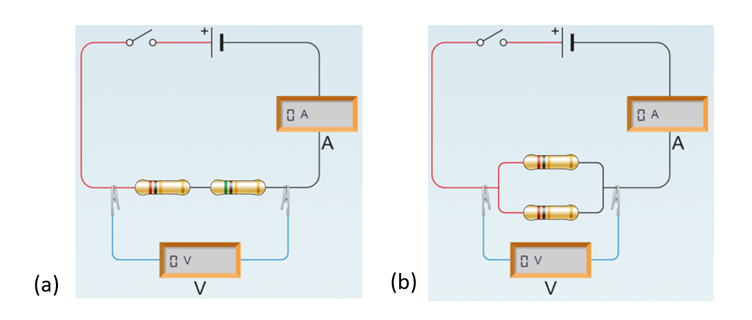
Figure 3. (a) Resistors in series (in line). (b) Resistors in parallel (side by side).
You may have noticed that the resistors shown in Figure 1 each have four colour bands. This is a coding system used to indicate the resistance and the quality of the resistor. Figure 4 shows the four-colour band table commonly used for carbon resistors.
The first three bands of the four-band colour coding system indicate the resistance value and the final band, set slightly apart, is the tolerance – a measure by how much a resistor may deviate from the stated resistance (the lower the tolerance rating, the closer the resistor will be in terms of the stated resistance value). The example resistor shown in Figure 4 has red/black/gold bands for its resistance value. The red gives the number ‘2’, the black a ‘0’ and the gold a multiplier of ‘x0.1’. The resistance is read as:
20 x 0.1 = 2 Ω.
The fourth and final band is gold, and this gives a tolerance value of ±5% – meaning that the resistor will have a resistance that is 2 ±5% Ω (a range of 1.9 to 2.1 Ω).

Figure 4. The four-band colour coding system used to indicate the resistance and tolerance (quality) of carbon resistors. This coding system is used because resistors are too small for numbers and tolerance values to be printed on them. The example resistor shown is a 2Ω resistor.
|
Resistors (re-visited) |
|
Use the four-band colour code chart shown in Figure 4 to work out the resistance and tolerance for each of the resistors shown in Figure 1. |
Wire also has a resistance, and this is determined by the length of the wire, its cross-sectional area and the material it is made from. You may have wondered why lightning conductor rods attached to tall buildings are made of copper – this is because it is a better conductor than iron.
In the practical activity associated with this lesson you will explore how the length and diameter of a nichrome wire affects resistance. Nichrome wire is made from mainly nickel and chrome and has a high resistance rating – as a result it tends to heat up when high currents are passed through and consequently is used as the heating element in toasters and hairdryers.
Previous: Lesson objectives Next: Practical activity