9 Sending data across the LAN
- Your home network provides access to both the devices you have installed within your house, and to the Internet via the WAN connection provided by your ISP. Before considering how data is sent to and from the WAN, we will examine how devices within the home network exchange data.
- Consider the home network shown below, where PC1 is sending a file to a printer connected to the network:
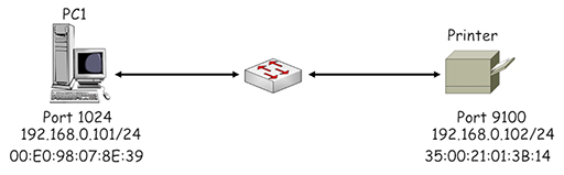
Figure 11
- Both PC1 and the printer are using IP addresses within the private range of addresses in IP network 19.168.0.0/24. The printer is listening on a registered port of 9100 and the PC has selected registered port 1024 to identify its TCP session with the printer. Both devices are fitted with an Ethernet NIC card, which have manufacturer assigned MAC addresses.
- PC1 first performs a check on the planned source and destination addresses to see which IP networks they are within:
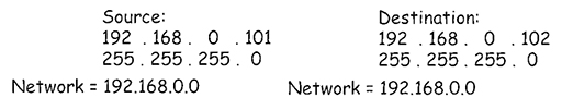
Figure 12
- PC1 uses its own subnet mask (/24 – 255.255.255.0) to determine the IP network that it is within. The mask identifies the first three octets of the IP address as belonging to the IP network address: 192.168.0. It then simply adds a ‘0’ to the end to complete the address: 192.168.0.0. PC1 then uses the same subnet mask to see which IP network the destination address is within and achieves the same result, 192.168.0.0.
- PC1 recognises that the source and destination IP addresses are within the same IP network, so there is no requirement to forward them to a default gateway (the home router) for delivery to a different IP network.
- PC1 encapsulates the print information into a succession of TCP segments, which are then encapsulated in appropriately addressed IP packets. The source address identifies PC1 (192.168.0.101) and the destination address identifies the printer (192.168.0.102):
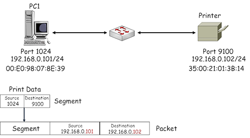
Figure 13
- The packet needs to be encapsulated within an Ethernet frame by the NIC on PC1. This appears to be straightforward until you consider the destination MAC address field. How does PC1 learn the MAC address burnt into another device’s NIC?
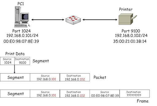
Figure 14
- At this point, PC1 is unable to identify the correct MAC address to place in the destination field of the frame, so the frame cannot be transmitted to the printer. Consequently PC1 initiates a broadcast communication to all the devices in its IP subnet using the Address Resolution Protocol (ARP), requesting information about the MAC address associated with the device using IP address 192.168.0.102:
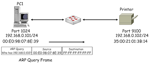
Figure 15
- Note the destination address used by the ARP is FF:FF:FF:FF:FF:FF – this is a broadcast address, which is flooded by the Ethernet switch from all its ports (apart from the one the address was received on). Thus, all the devices within the LAN receive the ARP query, but only the printer responds as the query contains its IP address. It returns an ARP response, identifying its assigned MAC address:
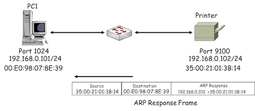
Figure 16
- PC1 uses the MAC address received in the ARP response to complete the destination MAC address field in the frame it is using to send data to the printer:
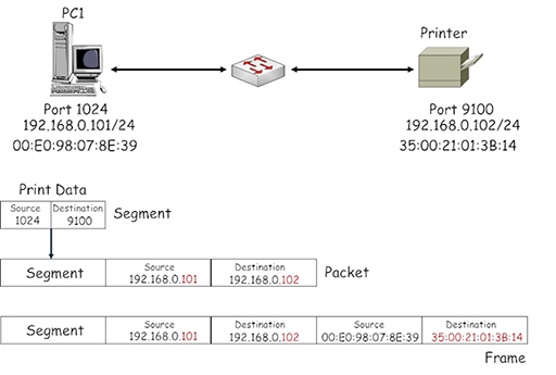
Figure 17
- Because ARP uses a broadcast destination address it can have a large impact on the operation of Ethernet switches, which are required to flood multiple copies of it from all their ports. To ease this burden, PC1 creates a local table called an ARP cache in which it stores all the IP address/MAC address pairings it has learnt. As a result, subsequent frames created by PC1 addressed to the printer will use the ARP cache to find the required destination address instead of using ARP.
- The entries in the ARP cache have a lifetime associated with them, which is constantly updated while the device is sending frames using the entries. Once the device stops sending frames the entries will timeout and be removed from the cache. This prevents the cache becoming full of outdated MAC address information.
Back to previous pagePrevious
8 Cellular wireless