10 Sending data to the WAN
- When your home devices forward data towards the Internet, they use source and destination IP addresses that sit within different IP networks, so the data must be forwarded via the default gateway (home router). Consider the network shown below, where PC1 wishes to access the WWW server:
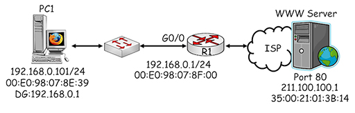
Figure 18
- PC1 performs a check on the planned source and destination addresses to see which IP networks they are within by comparing them with its own subnet mask:

Figure 19
- PC1 recognises that the destination address is on a different IP network and that it must send packets via the default gateway it has been configured to use: 192.168.0.1. PC1 encapsulates the webpage request into a succession of TCP segments, which are then encapsulated in appropriately addressed IP packets. The source address identifies PC1 (192.168.0.101) and the destination address identifies the web server (211.100.100.1):

Figure 20
- Why doesn’t PC1 use the address of the default gateway (192.168.0.1) as the destination of the packet? Remember that IP addresses are used to provide end-to-end connectivity between devices located on different IP networks – they are not used to identify any intermediate devices through which the packet is forwarded. PC1 therefore encapsulates the packet within an Ethernet frame and uses its destination MAC address to deliver the frame to the default gateway.
- Once again, PC1 uses ARP to determine the MAC address being used by the interface with IP address 192.168.0.1:
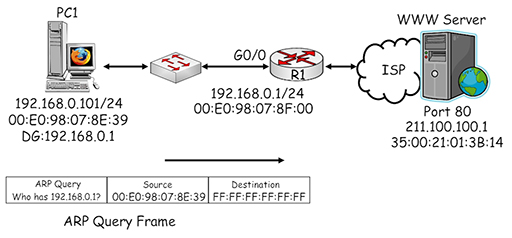
Figure 21
- The ARP query generated by PC1 is sent in a broadcast frame and delivered to all the devices in the home LAN. R1 recognises its own IP address within the ARP query and returns an ARP response providing its MAC address:

Figure 22
- PC1 uses the MAC address it received in the ARP response to complete the destination MAC address field in the frame it is using to send data to the default gateway:

Figure 23
- The frame is delivered across the local network to the gigabit interface of the home router, R1. Because the destination MAC address of the frame matches the MAC assigned to the interface, the router accepts the frame and de-encapsulates it to recover the packet. The router then tries to match the destination IP address with an entry within its own routing table so it can make a forwarding decision:

Figure 24
- The image above shows the home router in slightly more detail, including the routing table which contains two entries. The devices within the home network are connected to the router via the G0/0 interface, so network 192.168.0.0/24 appears directly connected. The second entry shows a default route, connected to the external WAN interface G0/1. It may look strange as it consists of an all zero IP address and subnet mask. However, this means that it will match all possible destination IP addresses and forward them from interface G0/1 towards the ISP.
- Why is a default route required? Remember, a router will only forward a packet if it finds a match for its destination IP address within the local routing table. If the home router did not use a default route it would need to have an entry for every possible destination network within the Internet, and it simply does not have enough memory to do that.
- By using the default route to forward all packets to the ISP, home users are relying upon the routers within the service provider’s network having sufficient routing information to be able to deliver their packets to the required destination networks.
- Once the router has determined that the packet needs to be forwarded from G0/1, it has three tasks:
- switch the packet to interface G0/1
- perform Network Address Translation (NAT) on the source address of the packet
- encapsulate the packet in an appropriately addressed frame.
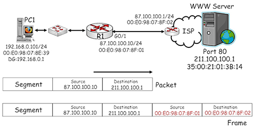
Figure 25
- The diagram above shows more detail about the connection between the home router and the ISP. The G0/1 interface is connected via whichever broadband technology is being used (DSL, cable or wireless) to a router within the ISP, which is configured with IP and MAC addresses.
- Referring to the diagram, note that the source IP address of the packet has been converted by NAT to 87.100.100.10, which is the public IP address that uniquely identifies the home router within the Internet.
- The packet is then encapsulated within an Ethernet frame, which uses the MAC address of home router interface G0/1 as its source and the MAC address of the ISP router interface as its destination.
- Subsequent routers that forward the packet towards the WWW server will not change the source IP address, otherwise reply packets would not be able to locate the home router.
- The packet will be encapsulated in a new frame every time it is forwarded by a router. The frames that are used may not be Ethernet – it depends on the type of WAN technology that is utilised by the devices which forward the packet to its destination.
- Another function provided by routers is to limit the spread of broadcast traffic such as ARP. Imagine what would happen if ARP could be propagated across the Internet – every time an ARP was generated, on any device, it would be sent to every other device in the world. This is obviously extremely undesirable and router interfaces create a broadcast domain – they will examine broadcast traffic, but they will not forward it onto other networks.
Back to previous pagePrevious
9 Sending data across the LAN