
Find out about The Open University's Science courses and qualifications
A crystal set is the most basic type of radio receiver. It is capable of receiving AM (amplitude modulated) transmissions, which are generally found on the long, medium and short wave bands.
The magic of the crystal set is that no power source is required; a tiny fraction of the transmitted signal provides sufficient power for the signal to be heard. What follows, while listing the parts you'll need, isn't a step-by-step how to guide, as part of the fun in building a crystal set is experimenting and optimising performance.
Aerial
Unless the crystal set is very close to the transmitter, an aerial, (or antenna) will be required in order to receive a big enough signal for the crystal set to work. Generally the aerial will be a length of wire, which should be as long and as high as possible.
A wire strung from an upstairs window to a distant tree will work well; say 30 metres long and seven metres high. The type of wire is not critical, but PVC covered stranded copper wire of about 2 milimetres diameter will work well.
If the wire is too thin it may break in the wind, and/or birds may fly into it; too thick and it will sag under its own weight.
The aerial should be insulated at each end from its support, a short length of washing line or other non-conductive cord can be used. An effective aerial will produce about one tenth of a volt radio frequency (RF), which will result in good reception.
Earth
An earth connection is required to complete the aerial circuit. This can be a length of copper pipe driven into the ground, or a length of buried un-insulated wire.
As with the aerial, a better earth connection will improve reception. It is possible to connect to a metal heating or water pipe, but this is not recommended on safety grounds should there be an electrical fault. For the same reason, the mains earth should not be used.
When the crystal set is not in use the aerial should be connected directly to the earth connection. This will prevent any possible static build up on the aerial.
Tuned circuit
The aerial and earth are connected across a parallel tuned circuit. The purpose of this is to select the wanted station.
A simple crystal set will not have good selectivity so if two strong signals are received on nearby frequencies it will not be possible to separate them.
The tuned circuit comprises a coil (inductor) and a capacitor, which is usually variable for tuning. Pre-wound ferrite rod coils can be bought, or you can wind your own: for example, for medium wave, 100 turns of 0.5 milimetre enameled copper wire wound on a toilet roll or similar sized non-metallic former, twisted/tapped every ten turns.
The greater number of turns, the longer the wavelength (lower frequency), so a coil for long wave will require more turns. If using a pre-wound ferrite rod, ignore the small link windings.
An air spaced variable capacitor (with a value around 500 picofarad) removed from an old radio is ideal, or alternatively a small polyvaricon capacitor as used in transistor radios.
Variable capacitors often have two or more capacitors in one (known as ganged), in which case these can be connected together to increase the maximum capacitance (lower the tuning frequency).
Some variable capacitors also have FM (VHF) tuning sections included, which can be ignored. If a variable capacitor is not available, a fixed capacitor can be used (e.g. 150 picofarad - 470 picofarad), with the tuning adjusted by changing taps on the coil. In which case, taps every five turns would be useful.
Detector
The purpose of the detector is to recover the audio signal (waveform) from the radio frequency signal. Early crystal sets used an adjustable ‘cats whisker’ detector, but a germanium or Schottky diode is now used, examples are OA90, OA91, BAT81, BAT85, 1N34, 1N5711. Any one of these can be used.
Silicon diodes, (such as 1N4148) do not work as well due to their higher forward voltage drop. Modern zero gate threshold voltage FETs can be used for better sensitivity, although these are not readily available in small quantities. The detector diode is polarized (directional), but in the crystal set circuit it does not matter which way round it is connected.
Headphones
Traditional crystal sets used sensitive high impedance headphones, typically several thousand Ohms, which are hard to obtain now. A crystal earpiece can be used, or a sensitive pair of walkman style headphones (usually 32+32 Ohms) connected through a transformer (e.g. type LT700) to raise the impedance. Low impedance headphones will ‘load’ the tuned circuit excessively.
Look for headphones with a high sensitivity figure, for example 115 decibels - a higher number indicates higher sensitivity; CPC AV03626 106 decibel headphones work well. Be aware that a higher quoted decibel specification does not always guarantee higher sensitivity in practice.
Note that if a crystal earpiece is used, a resistor (such as a 47k Ohms) may need to be connected across it to provide a DC path for the detector diode.
Construction
The fine detail here is left to the builder. Component leads can be soldered, or twisted together, or ‘crocodile clips’ can be used to make connections.
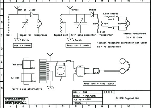
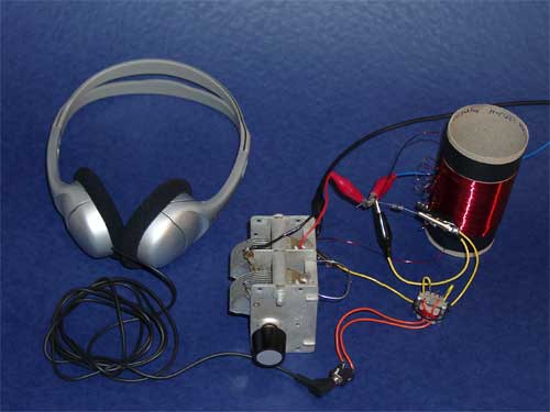
The diagram above (here is a link to a larger version), and the photograph at the top of the page, offers some guidance.
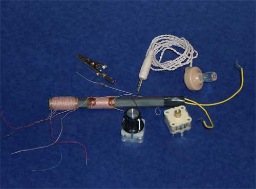
This photograph shows examples of alternative suggested parts. The components can be lashed together initially for experimentation, then connected more permanently and housed in any suitable enclosure once the crystal set is working.
Typical performance and troubleshooting
In the UK it will normally be possible to pick up two or three stations on medium wave, and/or BBC Radio 4 from Droitwich on long wave. If nothing at all is heard check:
- that all connections are sound, and ensure the enamel insulation on coil wire has been removed by being scraped off where connections are made
- that the correct connections for each component have been used
- that the tuning capacitor vanes are not bent and touching together.
If you get weak reception it may be that you need to improve the aerial / earth connections, or try a different pair of headphones.
Discover more content on radios
-
Interviews - Writing For Radio
Listen now to access more details of Interviews - Writing For RadioGet some advice on how to write a radio script from those that work in the industry.

Study a free course
-
Particle physics
Learn more to access more details of Particle physicsThis free course, Particle physics, will give you an overview of current concepts and theories in the field. You will learn about the fundamental components of matter – known as leptons and quarks – and the composite particles, such as protons and neutrons, which are composed of quarks. You will see that all particle reactions may be described ...

-
Discovering chemistry
Learn more to access more details of Discovering chemistryChemistry lies at the centre of our modern life, playing a part in areas as diverse as the development of new drugs and materials, analysing our environment through to more mundane activities such as washing your clothes and making your tea. But to truly understand the role chemistry plays you need to have a sound grasp of a number of ...

-
Introducing computing and IT
Learn more to access more details of Introducing computing and ITExplore how computing and IT shape our digital world with this free introductory course. Learn how computers work, how data is stored and deleted, and why online safety and data security matter while gaining a deeper understanding of how technology influences the way we live and think.

Rate and Review
Rate this article
Review this article
Log into OpenLearn to leave reviews and join in the conversation.
Article reviews