3 Digital camera
The last computer to look at in this session is the embedded computer in a digital camera.
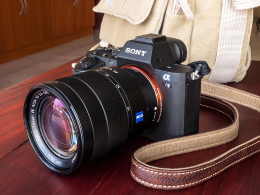
Figure 5 shows a picture of a digital camera. Inside the camera there is a memory card within the camera. This memory card is not the camera computer’s main memory, nor is it the secondary memory used to hold the computer’s program; it is a form of removable secondary memory where the computer stores the images taken. The memory card can be removed from the camera and another memory card inserted.
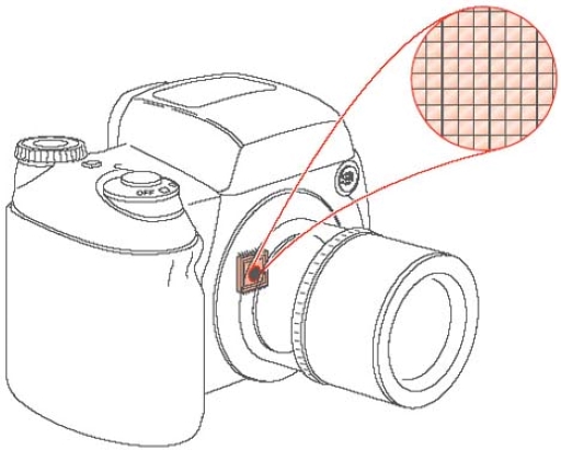
When the user presses the button to take a picture with a digital camera, its shutter opens, and the lens system focuses light from the image being photographed onto a light sensitive sensor. Two forms of light sensitive sensors are in common use: a charge-coupled device or CCD and complementary metal-oxide-semiconductor or CMOS sensors.
The two types of device work in the same way. They consist of a two-dimensional array of tiny light-sensitive cells that convert light into electrical charge. Figure 6 shows this array of cells and how the sensor is located behind the camera lens. The brighter the light that hits a cell, the greater the electrical charge that accumulates at that site. Once the camera shutter has closed, the information stored in the form of electrical charge at each cell is converted into a binary code and stored in the form of 1s and 0s in the camera’s memory, and this forms the image captured by the camera. To collect colour information a system of colour filters is placed over the cells of the sensor.
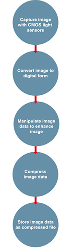
This stored raw data representing the image is then processed. The colour is reconstructed and adjusted, and techniques are used to sharpen the fine detail. The result of this process is a picture ready to be stored as a file in the camera’s secondary memory. To reduce the amount of stored data, the file is usually compressed – that is, the number of bits used to represent the image is reduced. In some cameras the user can select options to choose the type of compression carried out. The process of compression is described later in this block.
In the example here, we follow the practice of most users and have the computer in the camera to do the image processing. Professional and serious enthusiast photographers will often take the raw image from the camera and process it in a far more powerful PC with a large monitor attached. This allows them greater control of the image processing process, with the ability to see fine detail as they make changes directly.
Figure 7 shows the actions that the digital camera performs when taking a picture. Note that this diagram is not a functional block diagram of the camera but shows the actions that must occur to take and store the picture, in the order in which they must happen. The digital camera shown in Figure 7 has some buttons that allow the user to set particular conditions when taking a picture. In addition to the button to take a picture, there are buttons to set the flash, control the preview of the stored images on the screen and control the zoom lens and so on. As there is a flash facility, there must also be a light-level meter incorporated into the camera; the level of light falling on the meter determines whether the flash will operate.
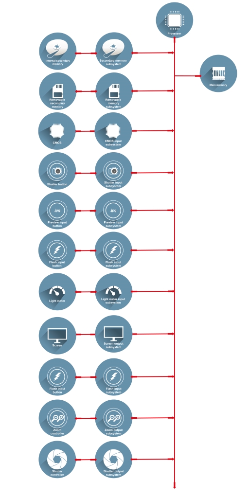
As with the PC and the electronic kitchen scales, a specific form of functional block diagram can be created for this digital camera.
Activity 3
Using the information about the digital camera given above, draw the specific functional block diagram for this camera.
Discussion
This computer has main memory and also two items of secondary memory: the removable memory card and the internal secondary memory. The input devices are the light sensor plus the buttons to take a picture, preview the stored images, set the flash and so on. The light meter is also an input device. The output devices are the camera’s screen, the flash mechanism, the zoom and the control to open and shut the shutter. (If you are a camera enthusiast you may also have thought of the various controls for the shutter aperture, the focus etc., but as these are not explicitly mentioned them in the text they are not included in the answer.)