

2 Electronic kitchen scales
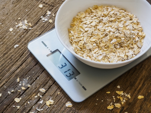
A set of electronic kitchen scales is shown in Figure 2. Their basic operation is relatively simple. When they are switched on and, for example, a 500-gram object is placed in the scalepan, the display shows the digits 500 and the letter g. Using a bowl on the scales allows for weighing many individual objects like the oats in Figure 2.
It might be possible to think of these electronic kitchen scales as a computer, in the sense that that they have hardware in the form of a processor, memory, input devices and subsystems, output devices and subsystems; and they have software in the form of programs. But they are not normally thought of in such terms because the fact that they are a computer is not of primary concern to the user – it seems more natural to think of them as kitchen scales. The term embedded computer is sometimes used when a computer is ‘invisible’ in this way. Objects like the kitchen scales are said to ‘contain’ a computer, rather than to ‘be’ a computer – the computer is thought of as being ‘embedded’ in the object.
For the electronic kitchen scales, a key input device is a sensor placed beneath the scalepan. This sensor measures how far the scalepan moves when an object is placed on it, and then generates a signal to represent this change of position. The sensor’s subsystem then converts this signal into binary coded data (that is, a pattern of 1s and 0s) that the processor can read and manipulate.
The seven-segment display on the scales is an output device. Its subsystem takes binary coded data from the processor and manipulates it into another binary form that will make the correct digits and letter appear on the display.
The processor in this system is performing a very simple task. Whenever the scales are switched on the program installed in the computer’s main memory at manufacture runs. This program first instructs the processor to pick up the data placed on the computer bus by the input subsystem. The program then tells the processor to use this data, plus some data stored in main memory, to generate some further data. This new data is then taken from the bus by the output subsystem.
The computer is essentially taking a signal in one format from the sensor and translating it into another format which enables the display to show the correct digits and letter. It is important that it does this in a time-span acceptable to the user.
Activity _unit6.3.1 Activity 1
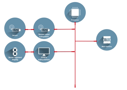
Using the information about the scales given above, create a functional block diagram for the kitchen scales. Note that these scales have no secondary memory.
Discussion
Here is an example answer:
In products such as these electronic kitchen scales the capabilities of the processor can be used to implement additional features. In this case the scales have a count-down timer so they can be used as a kitchen timer, and they can measure in imperial units (pounds and ounces) as well as metric units. They also implement an add-and-weigh function which allows the user to set the scales’ display to zero when there are some ingredients in the scalepan, making it possible to weigh the next ingredient without having to perform any mental arithmetic to add its weight to that of the ingredients already in the scalepan.
Activity _unit6.3.2 Activity 2
How might the input and output devices of the scales have to change if a countdown timer, a choice of measuring units and an add-and-weigh feature are all to be implemented? How would this change the diagram you drew for Activity 1?
Discussion
The user would need some way of setting the timer, of telling the system whether measurements have to be displayed in metric or imperial, and of switching on and off the add-and-weigh feature. Input buttons would be needed for each of these tasks: to set the timer, change the system between metric and imperial and operate the add-and-weigh function.
A beeper would be needed, to sound when the timer has counted down to zero. The output display would have to have additional functionality; for instance, it would have to show ‘oz’ and ‘lb’ for ounces and pounds when operating in imperial mode as well as ‘g’ for grams when operating in metric mode metric.
Additional input and output devices and their subsystems would have to be added to the diagram to represent the buttons used to set up the new features (inputs) and the beeper (output).
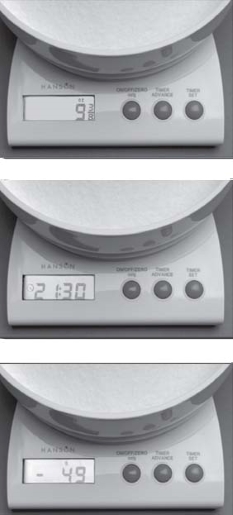
Figure 4 shows three photos of the scales’ display, each illustrating a different use. The top figure shows the display giving a reading in ounces; note that it displays fractions of an ounce. The middle figure shows the clock display; note that a colon is used in addition to the standard set of digits from 0 to 9. The bottom figure shows a weight displayed as a negative value. It may seem strange to have a ‘negative weight’, but it can occur when the add-and-weigh facility is used. Imagine that some ingredients are placed on the scalepan and the display reads 49 g. The user then invokes the add-and-weigh facility, so the display changes to 0 g. If the ingredients are then removed from the pan the display will read−49 g.
To implement these additional features the scales’ computer has to represent all the additional data that could be output on the display by predetermined codes consisting of 1s and 0s. It has to represent fractional data, negative numbers, a digital clock format and patterns to illuminate lb’ and ‘oz’ as well as ‘g’.