
Pre-weld stage

Components to be welded are placed in friction welding machine. Surfaces to be welded can be turned, sawn or sheared as long as they are square. One component is then rotated whilst the other is held stationary.
First friction stage

One component is advanced into pressure contact with the other. This initial "first friction stage" is at a low pressure, which minimises initial torque on the welding machine and electric motor, as well as squaring and preparing the faces for the next stage. There is very little "burn-off" during this stage, which is held for a fixed time depending upon the material and component size.
Second friction stage
The pressure is increased, and friction increases the temperature of the splayed surfaces, to give the required degree of plasticity and heat input whilst the weld zone stays below the melting point of the metals. This stage is held for a specific time, or usually, until "burn-off" of a specific length of component is achieved. The "burn-off" removes surface contaminants and enables a tighter length tolerance control.
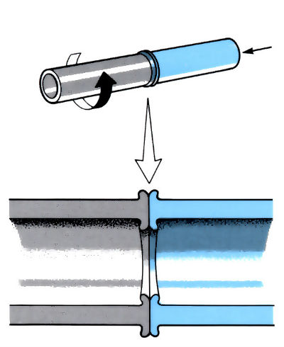
Forge stage

In the "forging stage" the rotating component is brought to a controlled stop, whilst the pressure between the components is rapidly increased. This causes a reduction in component length; the degree of reduction being called "forge collapse". The forging time depends on the material and weld size. The axial load is held until the temperature at the weld interface has dropped below the plastic level.
Friction welding cycles

Manufacture:
- An alternative to manual metal and gas metal arc welding, electron beam and laser welding.
- Capable of joining similar and dissimilar ferrous, non-ferrous and polymeric materials with the minimum of preparation, no consumables and no preheating.
- Two types of friction welding machine: (a) energy from a continuously running electric motor and (b) kinetic energy stored in a rotating flywheel.
- Production rates depend on number of welds per cycle, weld area, material and method of loading and unloading; typical rate 1–4 welds min-1.
- In-cycle upset removal, by shearing or turning, increases weld cycle by 5–20%, but may reduce overall costs, since it is easier to remove hot materials in their soft state.
- Production parameters and machine sizes depend on material, component geometry and surface area.
- Process not usually economical for small production runs, due to high capital cost and high output of machines.
- Production parameters not critical, hence the process is easy to operate under “production conditions”.
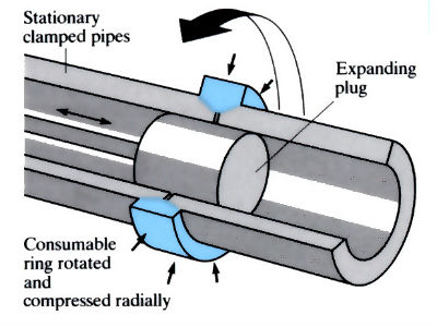
- Long lengths of pipe are joined using “radial friction welding”, in which a solid consumable ring of compatible material is rotated between the ends of the two stationary pipes.
Materials:
Materials can be conveniently classified according to their “friction weldability”, as follows, in order of decreasing weldability:
- Group A. Materials with mechanical properties not greatly affected by the heat-affected zone, which undergoes grain refinement due to hot working, e.g. commercially pure metals, solid-solution alloys, mild steel. Post-weld heat treatment is usually unnecessary, but for steels this depends on the carbon equivalent value.
- Group B. Heat-treatable alloys with mechanical properties affected by the welding process: e.g. plain carbon steel, alloy steel and precipitation-hardening Al-alloys.
- Group C. Materials which form brittle alloys or intermetallic compounds at the weld interface. This intermediate layer can usually be controlled to a few micrometers: e.g.: copper/steel, nimonics/steel and titanium/aluminium.
- Group D. Materials which produce sound joints when welded, but where the joint deteriorates during heat treatment or service, due to interdiffusion between the two materials: e.g. austenitic and ferritic stainless steel. This can sometimes be prevented by inserting a barrier; austenitic and ferritic stainless steels an be successfully welded using a nickel barrier.
- Group E. Materials with poor inherent weldability, or poor weldability due to “impurities”, such as sulphides and other non-metallic inclusions: e.g. grey cast iron and free cutting steel.
Design:
- Process most suitable for components of circular cross-section.
- Non-circular components may be joined by “orbital friction welding machines”.
- A wide variety of joint designs are possible in solid and tubular components.
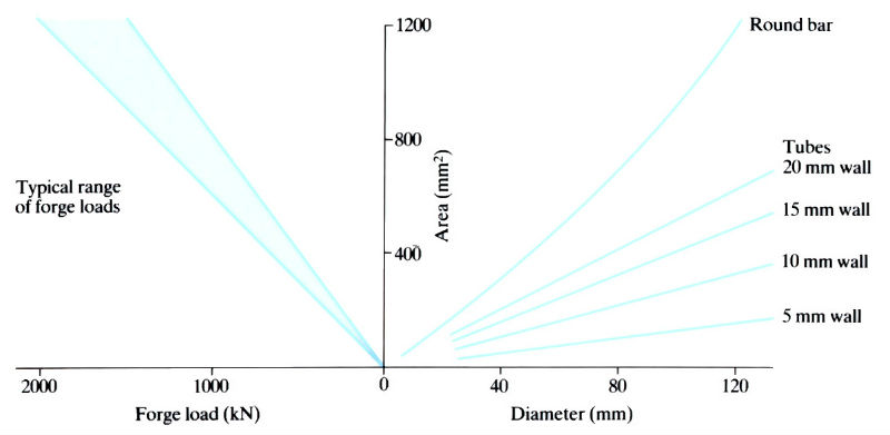
- Sizes range from 5 to 120 mm o.d. in solid, or 10–250 mm o.d. in tube. Weld areas vary from 500 to 20,000 mm2.
- Tolerances depend on the initial precision of components to be welded, but with accurately pre-machined parts, an axial alignment of ±0.001 rad is possible. Sawn or sheared faces give lower tolerances.
- Weldment lengths can be controlled to within ±2.0 mm.
Material optimisation using friction welded components


See Also: Manual metal arc welding, Gas shielded arc welding, Electron beam welding and Laser beam welding.
This article is a part of Manupedia, a collection of information about some of the processes used to convert materials into useful objects.
Rate and Review
Rate this article
Review this article
Log into OpenLearn to leave reviews and join in the conversation.
Article reviews