
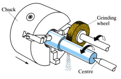
Conventional cylindrical grinding
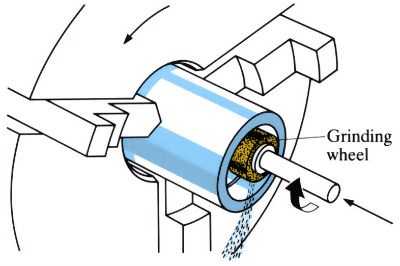
Conventional internal grinding
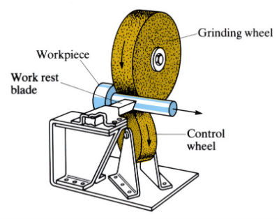
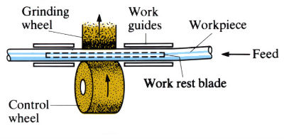
Principles of centreless grinding
Principles of internal centreless grinding
Centreless feed systems and applications
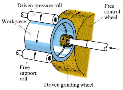
Through feed
Infeed
[[Missing image]]
End feed
[[Missing image]]
Manufacture:
Centreless grinding is used primarily for volume production and finishing, particularly for work which cannot be held between centres. There are several types of centreless grinding, all of which consist of three basic elements:
- Grinding wheel:
- The same types of grinding wheel are used for conventional grinding.
- Control (or regularity) wheel:
- This is a conventional rubber-bonded abrasive wheel on the same horizontal centre-line as the grinding wheel, which rotates in the same direction as the grinding wheel with a peripheral speed of 0.25-1 m s-1. The feed rate is varied by changing the angle and speed of the wheel.
- The centre heights of the grinding and control wheels are preset, and the diameter of the workpiece is controlled by the distance between them and the height of the work rest blade. The higher the workpiece above the centre-lines of the wheels, the faster it will be ground. However, if placed too high the workpiece will be lifted periodically from the work rest blade.
- Work rest blade or support roll (internal grinding):
- Often stellite faced to resist wear, with a 30˚ top face to keep the workpiece against the control wheel axis 12–25% of the work diameter above the centre.
External grinding
- Throughfeed grinding:
- Used for parallel work of almost any length. Can be used for straightening long workpieces of small diameter by placing centre of workpiece below the centre-line of the wheels and using a high traverse rate. After straightening, the workpiece is ground in the normal fashion.
- Ideally suited to automatic work feed and wheel dressing.
- Infeed grinding:
- A form of plunge grinding in which the work rest blade and control wheel are clamped in a fixed relationship to one another. The workpiece is placed on the rest blade against the regulating wheel, and is fed into the grinding wheel by means of an “infeed lever” whose travel distance determines the finished workpiece size. The lever is then reversed and the workpiece ejected. Ideally suited to fast production rates and automatic control. For large numbers both wheels are dressed to the required form, but for small numbers only the control wheel need be dressed.
- Endfeed grinding:
- The grinding wheel, control wheel and work rest blade are all fixed, and the work is fed in from the front up to a fixed stop. Ideally suited to fast production rates and automatic control. For large numbers both wheels are dressed to the required form, but for small numbers only the control wheel need be dressed.
Internal grinding
The control wheel and grinding wheel move at the same speed, acting as a pair of friction wheels. Either the workpiece or the grinding wheel can be made to reciprocate. High production rates are possible with automatic gauging and control of bore size. One operator can “mind” several machines when they are running automatically.
Design:
- Throughfeed grinding:
- Parallel work of any length providing there are no surface obstructions.
- Infeed grinding:
- Multi-diameter work, or headed work which cannot be passed completely through the wheels. Tapered, spherical or other irregular profiles can be ground and several diameters of workpiece may be finished simultaneously.
- Endfeed grinding:
- Tapered work and headed work having a shank length too long for the wheel face, thus precluding infeed grinding. Diameters up to 200 mm, with tolerance of ±0.0025 mm.
- Internal grinding:
- The outside diameter must be ground first, since the internal diameter is generated from the external surface.
- A high degree of concentricity is possible, even with thin-walled tubes, since no work-holding devices are required.
- Surface roughness:
- Determined mainly by the grit size of the wheel, but also affected by wheel structure, feed and speed, and wheel dressing.
- Typical values lie in the range of 0.1–2µm Ra, although values as low as 0.035 µm Ra may be obtained in careful finishing operations.
- Tolerances:
| Parameter | Production (mm) | Precision (mm) |
|
Diameter |
±0.0025 |
±0.00065 |
|
Parallelism |
±0.0025 |
±0.00065 |
|
Roundness |
±0.0003 |
- |
|
Concentricity of stepped diameter |
±0.0065 | ±0.0025 |
Precision tolerances are far more costly to hold since they require first class machinery, wheels and operating procedures.
See Also: Grinding and Creep feed grinding.
This article is a part of Manupedia, a collection of information about some of the processes used to convert materials into useful objects.
Rate and Review
Rate this article
Review this article
Log into OpenLearn to leave reviews and join in the conversation.
Article reviews