
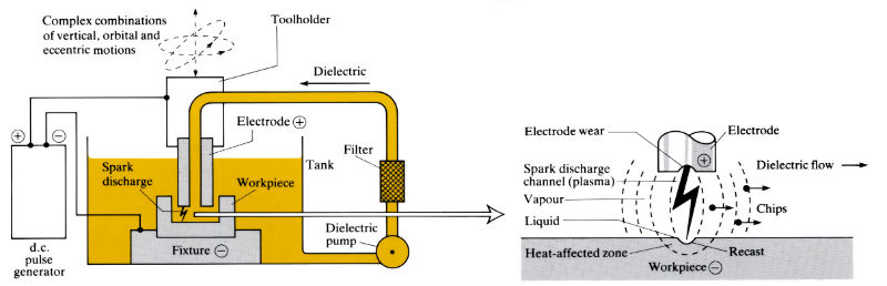
Electrical discharge machining
Removes any electrically conducting material by high frequency sparks that arc through a dielectric fluid flowing between the negatively charged workpiece and the positively charged, tubular or solid tool. The tool is servo-controlled to give a constant spark gap, and is capable of vertical, orbital or eccentric motion, or complex combinations of all three. The dielectric fluid cools the vaporised material into “chips”, which are then flushed away and filtered out. The spark produces a small crater in the workpiece with a “recast” and “heat affected” zone. These craters produce a “surface roughness” which decreases with reduced current and increased frequency. Erosion also occurs on the tool.
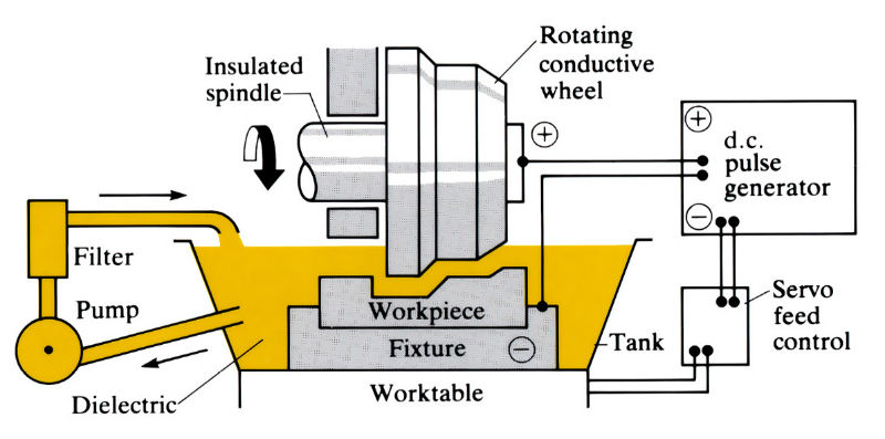
Electrical discharge grinding
Electrical discharge grinding is similar to electric discharge machining, but with the tool in the form of a rotating conductive wheel and with lower currents.
Manufacture:
- An alternative to ultrasonic machining (USM) and electrochemical machining (ECM).
- Frequently used for “one-off” tool and die production, but can be used in mass-production and transfer lines. Production rate low, i.e. aerospace applications.
- Many production parameters; most important are current, spark gap and frequency, dielectric type and flow rate tool (electrode) material and polarity.
- Metal removal rates vary with material and production parameters but are typically in the range 0.006–0.65 cm3 h-1 A-1.
- Currents vary from 0.1 to 5000 A (using multiple 500 A power packs).
- Tool material and polarity vary with workpiece material and production parameters. Common tool materials are graphite, copper, Cu/graphite, brass, steel, W and Cu/W. Tools should be designed to allow a good flow of dielectric and venting of any gases produced during machining. In some cases the tool and/or workpiece are vibrated to improve the flushing action of the dielectric.
- Tool manufacture is one of the most costly items of EDM. Tool “wear ratios” (workpiece erosion/tool erosion) vary from 0.5/1 to 100/1 (USM, 1/1 to 1000/1; ECM no appreciable tool wear). With certain combinations of electrode and workpiece material, under special operating conditions, “no-wear EDM” occurs, in which the wear ratio is <0.01. The most common combination for “no-wear” operation is a copper or graphite electrode and a steel workpiece.
Materials:
- Any electrically conducting material, irrespective of hardness. Hardened steel dies and other difficult-to-machine materials can be machined without distortion or the need for further heat treatment.
- Leaves a “recast” layer and heat affected zone (HAZ) 0.0025–0.15 mm deep which must be removed when fatigue and stress corrosion resistance are required.
- Leaves a residual stress in the surface which, although 0.025 mm deep, may be a high proportion of the tensile strength.
- Cracking can occur in some materials, and when using a hydrocarbon-based dielectric carbon pick-up may occur in steel workpieces, leading to a hard martensitic layer.
Design:
- Used extensively for tool and die work, and particularly suitable for irregular slots and cavities and small holes with high aspect ratios. Leaves no burrs.
- Holes down to 0.05 mm can be formed, but an allowance has to be made of 0.005–0.50 mm side-1 for “overcut”. Holes are usually slightly tapered (0.5–5 μm mm–1 side-1) due to sparking from the side of the tool, but this taper can be eliminated by careful tool design.
- Normal production tolerance is ±0.025 mm but ±0.005 mm is possible under ideal conditions. Corner radii of 0.4 mm are possible.
- Surface finish depends on production parameters, but is typically in the range Ra = 1.6–4.8 µm. Mirror finishes of Ra 0.05 µm are possible, and under roughing conditions Ra may be as high as 15 µm.
See Also: Grinding, Electrochemical machining and Ultrasonic machining.
This article is a part of Manupedia, a collection of information about some of the processes used to convert materials into useful objects.
Rate and Review
Rate this article
Review this article
Log into OpenLearn to leave reviews and join in the conversation.
Article reviews