
Electro-slag welding
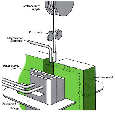
Electro-slag welding is used to butt weld together thick sections (>20mm). Sections to be joined are fixed in the vertical plane. Water-cooled copper shoes are pressed tightly against each side of the joint (at the bottom position of the start of welding) to prevent leakage of weld metal and slag. There may be one to three electrode wires continuously fed from spools. A self-adjusting arc is struck on to a run-off plate beneath a coating of flux. This is converted to liquid flux in about half a minute. A current is then transferred, not as an arc but through the liquid slag, which gives the same order of voltage drop as an arc would. Any excess slag loss is made up by a powder flow. Vertical traverse is achieved by rack and pinion.
Manufacture:
- Electro-slag welding is used for joining thick materials in the vertical plane.
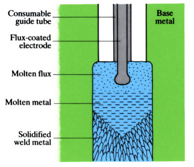
- It is not an arc process, depending on the electrical resistivity of molten flux to produce the heat necessary to melt both filler and base metal.
- As the flux melts, a slag blanket (2.5–3.8 mm thick) is formed. Current is conducted directly from an electrode wire through the slag.
- Process welds metal 20–2000 mm thick.
- Molten metal and slag are retained in the joint by water-cooled copper shoes that automatically move upwards as the weld progresses.
- Probes control the flow of granular flux from a hopper over the weld zone.
- Automatically controlled process.
- No joint preparation is required.
- Each wire used deposits 22 kg of weld metal per hour.
- Welding speed is 100 mm min-1 to weld plates 20 mm thick.
- Power supplies 450–1500 A a.c. or d.c. (15–50 kW).
- Deposit rates can be increased to 170 kg h-1 by addition of 120% metal feed powder of same composition as the feed wire (high speed electro-slag welding).
Materials:
- Process is used to weld hot-rolled carbon steel, low-alloy high strength steel, and quenched and tempered low-alloy steel.
- Can also be used to weld stainless steel and aluminium alloys if required.
- The weld metal acquires the structure of a casting, wherein the sizes and orientations of the grains are governed by heat removal characteristics. Long columnar grains can be formed with microsegregation and agglomeration of defects, such as slag, inclusions and gas porosity, along the grain boundaries. There is also a large heat-affected zone (HAZ). These poor structures give poor impact resistance in the weld area (ductile-brittle transition temperature of -18˚C).
- Addition of the following alloying elements to the feed wire help to increase impact resistance: 0.04% cerium, 0.2% each of manganese, chromium and nickel.
- Adjusting the composition of the flux to give a basicity of 0.5–2.0 by addition of 10–30% CaF2 and 10% Al2O3 also helps to improve impact resistance of the weld.
- Post-weld heat treatments can also improve the notch toughness values.
- Addition of metal powder with similar composition to the feed wire, plus the addition of FeTi and FeB also improve impact resistance.
Design:
- Process can only be applied to vertical, flat, butt-type welds.
- Used for welding thick plate sections (20–2000 mm thick).
- Used for welding ships, large containers and heavy engineering structures.
- Allowance for large amounts of transverse shrinkage on cooling, e.g. 5 mm on 50 mm thick plates.
See Also: Manual metal arc welding (MMA), Gas shielded arc welding.
This article is a part of Manupedia, a collection of information about some of the processes used to convert materials into useful objects.
Rate and Review
Rate this article
Review this article
Log into OpenLearn to leave reviews and join in the conversation.
Article reviews