
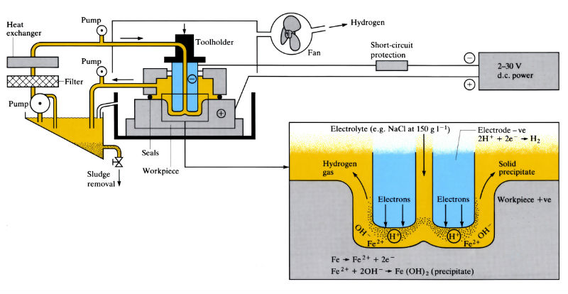
Electrical reaction (iron or steel workpiece)
Removes any electrically conductive material by the anodic dissolution of the workpiece (+ve) in a stream of electrolyte, which separates the workpiece from the shaped electrode (-ve) (tool). The tool has a constant feed rate matched to the rate of dissolution of the workpiece, which is formed into a mirror image of the tool. Metal is removed from the workpiece in accordance with Faraday’s law at a rate determined by the electrochemical equivalent of the metal.
Manufacture:
- An alternative to EDM and USM, best suited to complex shapes and repetitive production such as multiple hole formation.
- Automatic deburring and rounding of corners due to higher current densities at edges and corners.
- Operates at 5–30 V d.c. and current densities of 10–500 A cm- 2 (50–40,000 A).
- Removal rate approximately 1.64 cm3 min- 1 (1000 A) – 1, irrespective of material. The higher the current density, the faster the cutting rate and the better the surface finish.
- Feed rates vary from 0.5 to 15 mm min- 1, with a frontal working gap of 0.076–0.76 mm.
- Most common tool materials are brass, copper and bronze, but stainless steel, titanium, sintered copper/tungsten, aluminium and graphite are also used. Tool life is long compared with EDM and USM, since there is no appreciable tool wear. Tool material depends on component numbers, material and design, electrolyte composition and pressure, spark resistance, cost, etc.
- Most common electrolytes are sodium chloride (60–240 g l – 1) and sodium nitrate (120–480 g l –1), which requires special safety precautions.
- Electrolyte flow rate is approximately 1 l min- 1 (100 A) –1 with a velocity of 1500–3000 m min- 1 and a temperature of 25–45°C. Inlet pressures are 137–2060 k Pa, outlet pressures 0–310 k Pa.
- The anodic dissolution of the workpiece produces hydrogen, necessitating special safety precautions.
- Large quantities of “sludge” are formed which must be removed by filtration.
- After machining the workpiece must be cleaned and oiled to prevent corrosion.
- Complex internal ratchet forms in steel gear-hub cases have been produced at the rate of 15–20 hubs min – 1 using multipurpose Cu/W tooling.
Materials:
- Any electrically conductive materials, but best suited for high strength, hard (> 400 VPN) or difficult-to-machine materials.
- Component is stress free with no distortion, but has a lower fatigue life than that produced by stress-inducing processes such as USM.
- Poor operating conditions can lead to hydrogen pick-up in steels.
Design:
- Tolerances are highly dependent on component geometry, tool design and operating conditions. Typical accuracies are; for contoured cavities; ± 0.1 mm, and for frontal cuts or cutting with special tools; ± 0.025 mm.
- Holes down to 3 mm diameter. For smaller holes ESM and STEM can be used. Deep holes have a taper of 0.001 mm mm –1.
- “Overcut” is 0.13–1 mm, but can be almost eliminated with special tool design.
- Internal radii 0.2 mm, external radii 0.05 mm.
- Surface roughness typically 0.4–0.8 µm Ra, but “mirror finishes” of 0.1 µm Ra are possible with frontal cuts in certain materials. Side gaps are rougher due to the lower current density.
See Also: Abrasive jet cutting and Ultrasonic machining.
This article is a part of Manupedia, a collection of information about some of the processes used to convert materials into useful objects.
Rate and Review
Rate this article
Review this article
Log into OpenLearn to leave reviews and join in the conversation.
Article reviews