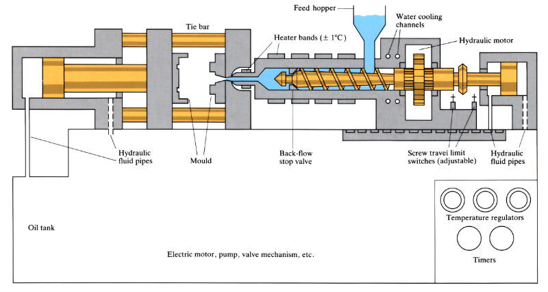
Manufacture:
- Process normally operates at pressures up to 200 MPa, although “high pressure” injection moulding machines, operating at 500 MPa, are currently under investigation (cf. low pressure die casting, 0.02–1 MPa; high pressure die casting, 3–200 MPa).
- Machines are classified according to the locking force of the platens and can vary from 1–3000 tonnes. Most machines lie in the range of 50–250 tonnes. The higher the locking force, the larger the projected area of the component that can be produced. Locking can be either mechanical or hydraulic, although mechanical locking is considered to give faster cycle times.
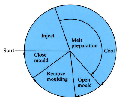
- A typical injection moulding cycle is shown below. It has been claimed that by reducing the floor cycle time from 25 to 24 s, 2 weeks of production time per year can be saved.

- Cycle times for reinforced thermosets are usually longer than for thermopolymers, although 30% better than in compression moulding and result in less porosity.
- Yields are high, varying from 95–99%. although the process is only 25–40% energy efficient.
- Due to the high capital cost of machines and dies, the process is only suitable for long production runs.
Materials:
- Thermopolymers are the most commonly used materials although the process is being increasingly used on thermosets (such as polyesters and melamines), rubbers, reinforced polymers (glass and carbon fibre) and to produce both structural and sandwich foams.
- Material is in the form of powder or granules (thermopolymers), strips (rubbers) and dough moulding compounds (DMC) for reinforced thermosets. Fibre lengths in DMC vary from 5–50 mm depending on the type of DMC, and the injection moulding method.
Polymer
Moulding temperature
To (°C)Freeze-off temperature
TF (°C)Freeze-off temperature
TE (°C)Demoulding temperature
TD (°C)LDPE 220 90 50 60 PVC 170 140 50 110 PP 250 135 50 105 POM 220 135 50 105 PS 230 130 50 100 ABS 230 140 50 110 PMMA 260 160 50 130 PPO 280 180 50 150 PC 310 200 50 170 Nylon 66 290 240 50 210 PES 360 250 70 220 PEEK 390 310 90 280
Design:
- Features such as moulded-in screw threads and undercuts (particularly in the draw-direction) should be avoided if at all possible, since they involve metal inserts or side-cores, which add significantly to the mould costs.
- Sprues should have a taper of 10°. There should be draw angles of 2.5° on the sides of the mouldings.
- Allowances must be made for material shrinkage, which is greatest with crystalline polymers.
Polymer Linear shrinkage (%) Amorphous polymers
PVC
0.2 - 0.5
PS
0.4 - 0.7
ABS
0.4 - 0.8
PMMA
0.4 - 0.8
PPO
0.5 - 0.7
PC
0.5 - 0.7
PES
~ 0.7
Crystalline polymers
LDPE
1.5 - 2.5
HDPE
1.5 - 2.5
PP
1.0 - 2.0
POM
~ 2.0
Nylon 66
0.8 - 1.5
PEEK ~ 1.0 - Components produced by injection moulding vary widely, from spoons, to hollow carbon reinforced tennis rackets, to small sailing dinghies with a projected surface area of more than 3.5 m2.
See Also: Low pressure die casting and High pressure die casting, Vacuum forming, Compression moulding and Superplastic forming.
This article is a part of Manupedia, a collection of information about some of the processes used to convert materials into useful objects.
Rate and Review
Rate this article
Review this article
Log into OpenLearn to leave reviews and join in the conversation.
Article reviews