
Laser cutting
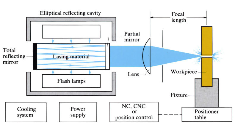
Removes material by focusing a laser beam onto the workpiece which is melted, ablated and vaporised at the point of impingement.
Gas-assisted laser cutting
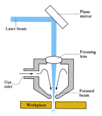
In gas-assisted laser cutting, a gas stream is simultaneously focused onto the workpiece. The gas can promote an exothermic reaction and so increase the cutting efficiency (as in the case of oxygen), or merely help to purge away the molten material and protect the workpiece (as in the case of argon or nitrogen).
Manufacture:
- An alternative to electron beam cutting, plasma arc cutting, water jet cutting, flame cutting and electrochemical wire cutting for profiling, cutting and drilling holes for slots in sheet materials. More suitable for large production runs under automatic or semi-automatic control than for small batches.
- Cutting, drilling, scribing, etching, welding and heat treatment can often be done using the same equipment by varying the production parameters.
- Most common lasers are CO2 (30% efficient, but bulky) and Nd-YAG (2% efficient, but compact). Beam is continuous or pulsed, the spot (diameter 0.01–0.30 mm) being focused on or slightly below the workpiece surface. Focusing accuracy is critical, particularly for thin, high melting point materials.
- Oxygen or air is the most suitable “assisting gas” for most metallic and non-metallic materials but helium, helium/argon or CO2 is used for titanium. Gas pressures vary from 140 to 825 kPa.
- Power varies from 0.25 to 20 kW, with power density 106–109 W cm-2. Some machines are capable of continuous variation throughout their range. For a given power, the higher the cutting speed, the better the cut quality and the less the “heat affected zone”.
- Accuracies and tolerances are limited mainly by the accuracy of the workpiece positioning. Workpiece fixture is simplified by the low inertia of the beam, non-mechanical contact and lack of cutting force. For trepanning large holes the beam is rotated, rather than the workpiece.
- The ability to direct and focus the laser beam enables cutting and drilling to be carried out in normally inaccessible situations.
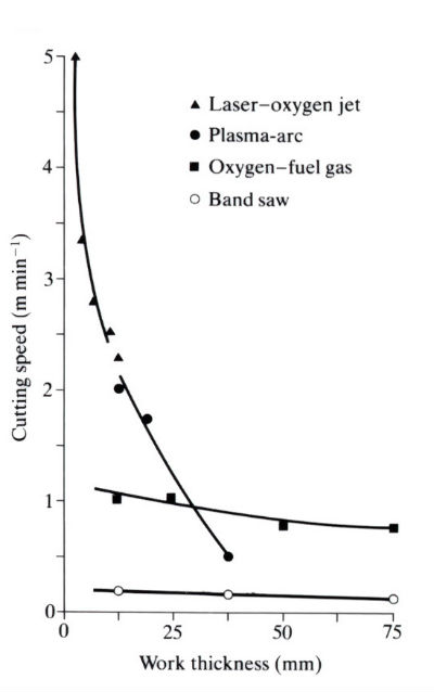
- Cutting speeds (usually greater than alternative processes) depend on material thickness, and the laser power and characteristics.
- Drilling rates can be fast: e.g. 0.5 mm dia., 2.5 mm deep hole in cobalt-based superalloy in 1–3 s.
- The vapour produced “solidifies” to form a fine dust which is a health hazard and requires removal. Eye protection is required by law for direct and reflected laser light.
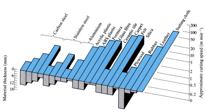
Guide to cutting speeds using a 1kW CO2
Comparative cutting speeds
Materials:
- Laser cutting is currently used on metals, glasses, ceramics, polymers, cloth, wood and paper in a wide variety of industries.
- In some materials a “recast” layer of 0.025–0.25 mm and a “heat affected zone” of 0.025–0.075 mm occur, together with a hardness alteration below the surface. Although less than any other thermal process, these surface effects should be removed or modified in components that are highly stressed and/or subject to fatigue.
- Due to high temperatures and rapid cutting speeds there is little heat dissipation in the workpiece, making handling easier and enabling cutting to be carried out close to heat-sensitive materials.
Design:
- Typically, holes 0.1–1.5 mm in diameter, with aspect ratio of 40/1 can be drilled at 6–90˚ to the surface, although under special conditions holes of 2 µm with an aspect ratio of 250/1 have been drilled. Larger holes are formed by trepanning.
- Holes or cuts up to 25 mm deep can be made, depending on workpiece material.
- Hole tolerance is +5% of the diameter and there is a taper of 5–20% of the diameter.
- Blind holes and slots can be cut in non-metallic materials only, due to the re-solidification of the vapour.
- When cutting sheet material the minimum outside radius is approximately 3 mm.
- Surface finish is typically 3.2–6.3 µm Ra.
See Also: Laser beam welding, Electron beam welding, Electrical discharge wire cutting.
This article is a part of Manupedia, a collection of information about some of the processes used to convert materials into useful objects.
Rate and Review
Rate this article
Review this article
Log into OpenLearn to leave reviews and join in the conversation.
Article reviews